How to Generate Activity Diagram from User Story?
In the world of agile, a user story can be used to record a user's problem or concern to be addressed by the system to be developed. During the discussion of user story, project team can write down the suggested usage of the system in the form of scenarios. Each scenario is a set of steps a user will take to achieve what they want, under that user story. With user story scenario, user can read and confirm if the system flow is what they preferred before the commencement of feature development.
Writing a User Story Scenario
- Create a new project with Visual Paradigm. Select Project > New from the application toolbar.
- In the New Project window, enter Online Shopping as the project name. Click the Create Blank Project button.

- Open the User Story page in UeXceler. If UeXceler is not already open, select UeXceler > UeXceler from the application toolbar and then open the User Story page.

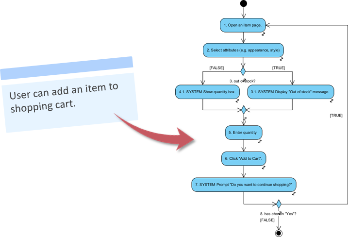
- Create a general user story. Click on Add a feature that can... and enter User can add an item to shopping cart. as the name.

- Double-click on the user story to open it.
- Open the Scenario page.

- Enter the steps to accomplish this user story. Click on the first step and enter Open an item page.

- Press Enter and enter step 2: Select attributes (e.g. appearance, style).

- A quantity box will be displayed when the item the user selected is still available for purchase. Let's write an if-then-else for this. Press Enter to go to the third step, then press Ctrl+Space to toggle the Statement Control list.

- Select If from the Statement Control list.

- Enter out of stock.

- Let's say the system will display an 'out of stock' message in this situation. Press Enter to go into the `if` condition, then press Ctrl+Space again.
- This step is performed by the system. Let's create a System Response. Select System Response from the Statement Control list.

- Enter Display "Out of stock" message.

- A quantity box will be displayed in the 'else' case. Now, press Enter and press Ctrl+Space to toggle the Statement Control list.
- Select Change to Else from the Statement Control list.

- Press Enter.
- Toggle the Statement Control list by pressing Ctrl+Space. Select System Response from the list and enter Show quantity box.

- Press the Down arrow key to go to the 'end if'. Then, press Enter to go to step 5.
- The customer will then enter the quantity of the item and add the item to the cart. Enter Enter quantity and Click "Add to Cart" as steps 5 and 6, respectively.

- Once the item is added to the cart, the system will prompt if the customer wants to continue shopping. Press Enter to create a new step. Enter the system response Prompt "Do you want to continue shopping?" as step 7.

- If the customer has chosen "Yes", the system will then reopen the item page. Use the Statement Control list to add an `if` condition: has chosen "Yes".

- Press Enter to go into the `if` condition. Press Ctrl+Space to toggle the Statement Control list. This time, select Jump.

- Click on the tiny arrow button next to step 1 to represent jumping to step 1.

Generating an Activity Diagram from a User Story
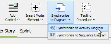
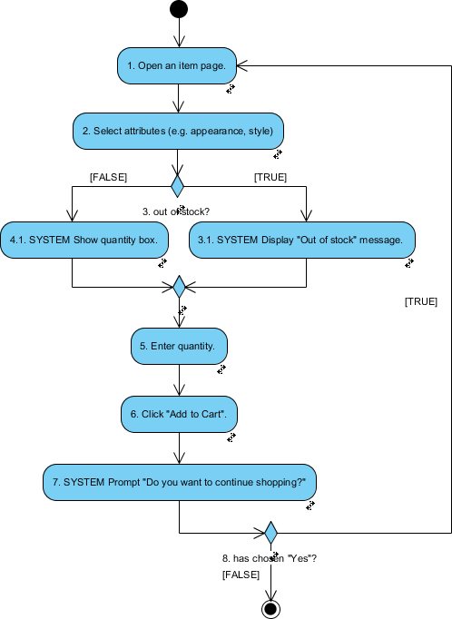
We have just completed the scenario. Let's generate a UML activity diagram from it. Select Synchronize to Diagram > Synchronize to Activity Diagram from the toolbar.
A UML activity diagram is generated from the scenario in seconds.
If necessary, press Ctrl+Tab to go back to the user story.