How to Visualize the Dependencies between Elements?
We analyze a model element when we want to identify its related elements so as to foresee the potential impact that may cause on the model resulted by modifying the model element. The term "related" here represents any kinds of connection that can have between two elements, such as a general to-and-from relationship, a parent-child relationship, transitor, or even a sub-diagram relationship with a diagram.
To analyze a model element
By analyzing a model element, you can know its relationships with other elements. To analyze:
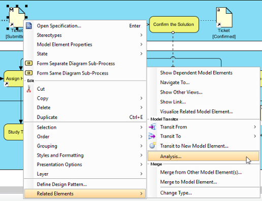
- Right click on the diagram element we want to analyze and select Related Elements > Analysis... from the pop-up menu.
Analyze a diagram element - The result of analysis will be presented in analysis diagram. In the Analysis window, either select Create new diagram to present the result in a new analysis diagram or select to present in an existing analysis diagram. The check boxes at the Analyse section governs the type(s) of relationship to be analyzed. Click OK when ready.
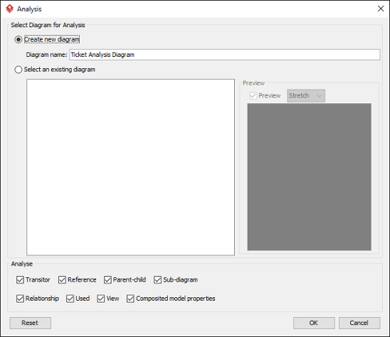
Create a diagram, or select an existing analysis diagram to present the result
Type Description Transitor The transited element of the chosen element or the element where the chosen element was transited from Reference The shape or diagram references of the chosen element Parent-Child The parent (e.g. package) or the child of the chosen element Sub-diagram The sub-diagram(s) of the chosen element Relationship The relationship(s) of the chosen element, such as association, dependencies, sequence flow, etc Used The connection with the chosen element, other than any other kinds of relationship types. For example, requirement owned by use case added through use case description is a kind of Used relationship. View The view(s) of a model element, which can be seen as the shapes of a model element Composited model properties The composited model element(s) of a model element. It means any property that composited another model element. An example would be Class's code details element. Kinds of relationships that can analyze - Unlike other diagrams, analysis diagram will not be saved in a project file by default. This means that when you restart the application, you will not see the analysis diagrams created before, no matter you had performed a project saving or not. If you want an analysis diagram be saved into the project, click the Make Persistable Now button below the breadcrumb of the analysis diagram. Once clicked, the diagram will be saved into the project file the next time you perform a project saving. Note that you cannot change a diagram back to not persistable. If you don't need the diagram anymore, consider to delete it.
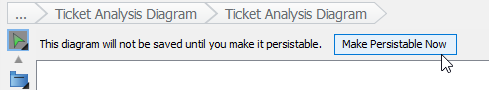
Making an analysis daigram persistable
Reading analysis diagram
The result of analysis is shown in an analysis diagram.
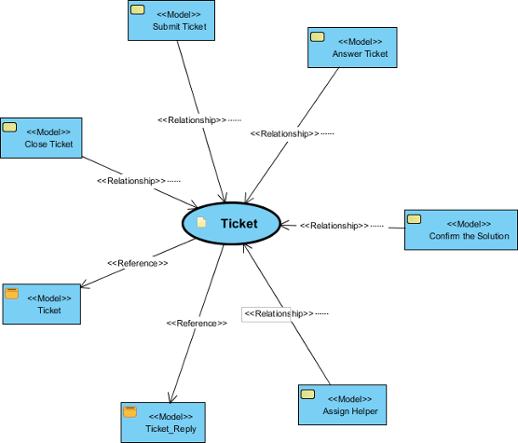 |
| An analysis diagram |
The oval node at the center of the diagram represents the element you have chosen to analyze, the connectors branching out are the relationships with the analyzing element and the nodes at the opposite end of connectors are the related elements.
Inside a node of a related element, you can see a tag (e.g. <<View>>) which represents the type of that related element. At the bottom part of a node box is the name of the related element.
By reading the diagram, you can identify the relationship of a model element and determine the impact that may act upon the model when modifying the model element.
Analyze further
Analysis diagram allows you to visualize the relationships between a model element and its related elements. If you want to visualize the relationship between a related element with its related elements, you can analyze further by performing the steps below:
- Move your mouse pointer over the related node in the analysis diagram.
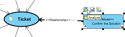
To analyze a task - Click on the Analyze resource.
- Select the type of relationship to be analyzed.
Note that by analyzing mutliple model elements on the same analysis diagram, the diagram may contain a lot of nodes and connectors, making it hard to read and understand. To solve this problem, you may consider showing the result in another analysis diagram by selecting Analyse in New Diagram... in the step above.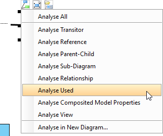
Analyse Used
Related Resources
The following resources may help you to learn more about the topic discussed in this page.
| Chapter 2. Analysis Diagram | Table of Contents | 2. Updating analyzed result |