EPC diagram |
|
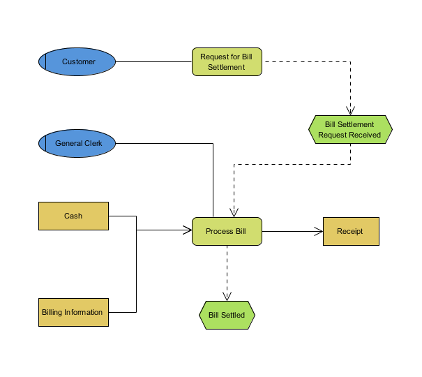
EPC diagram, short for event-driven process chain diagram, is a flowchart based diagram that can be used for resource planning and identifying possible improvements of a business process.
|
|
|
Business process diagram
|
Conversation diagram
|
Data flow diagram
|
EPC diagram
|
Process map diagram
|
Organization chart
|
|
|
|
|
EPC diagram |
|
|
|
Notation
 | | Event |  | | Function | |  | | And Operator |  | | Or Operator | |  | | XOR Operator |  | | Organization Unit | |  | | Control Flow |  | | Process Path | |  | | Organization Unit Assignment |  | | Information Resource | |  | | Information Flow | |
| DefinitionEPC diagram, short for event-driven process chain diagram, is a flowchart based diagram that can be used for resource planning and identifying possible improvements of a business process. |
|
| |
Event | | 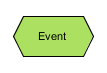 | | Definition | | An event describes what circumstances a function or a process works or which state a function or process results in. |
| | Properties | | | Name | The name of event. | | Documentation | Used to annotate the event, such as descriptions and other documentation. |
|
|
|
|
| |
Function | | 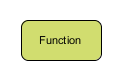 | | Definition | | A function describes the transformations from an initial state to a resulting state. |
| | Properties | | | Name | The name of function. | | Documentation | Used to annotate the function, such as descriptions and other documentation. |
|
|
|
|
| |
And Operator | |  | | Definition | | An and operation corresponds to activating all paths in the control flow concurrently. |
| | Properties | | | Name | The name of and operator. | | Documentation | Used to annotate the and operator, such as descriptions and other documentation. |
|
|
|
|
| |
Or Operator | |  | | Definition | | An or operator corresponds to activating one or more paths among control flows. |
| | Properties | | | Name | The name of or operator. | | Documentation | Used to annotate the or operator, such as descriptions and other documentation. |
|
|
|
|
| |
XOR Operator | |  | | Definition | | An XOR operator corresponds to making decision of which path to choose among several control flows. |
| | Properties | | | Name | The name of XOR operator. | | Documentation | Used to annotate the xor operator, such as descriptions and other documentation. |
|
|
|
|
| |
Organization Unit | | 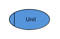 | | Definition | | An organization unit determines which person or organization within the structure of an enterprise is responsible for a specific function. |
| | Properties | | | Name | The name of organization unit. | | Documentation | Used to annotate the organization unit, such as descriptions and other documentation. |
|
|
|
|
| |
Control Flow | | 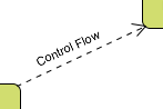 | | Definition | | A control flow connects events with function, process paths, or operators creating chronological sequence and logical interdependencies between them. |
| | Properties | | | Name | The name of control flow. | | From | The source of control flow. | | To | The target of control flow. | | Documentation | Used to annotate the control flow, such as descriptions and other documentation. |
|
|
|
|
| |
Process Path | | 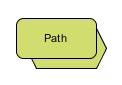 | | Definition | | A process path shows the connection from or to other processes. |
| | Properties | | | Name | The name of process path. | | Documentation | Used to annotate the process path, such as descriptions and other documentation. |
|
|
|
|
| |
Organization Unit Assignment | | 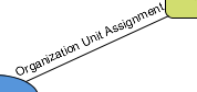 | | Definition | | An organization unit assignment show the connection between an organization unit and the function it is responsible for. |
| | Properties | | | Name | The name of organization unit assignment. | | From | The source of organization unit assignment. | | To | The target of organization unit assignment. | | Documentation | Used to annotate the organization unit assignment, such as descriptions and other documentation. |
|
|
|
|
| |
Information Resource | | 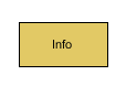 | | Definition | | An information resource portrays objects in the real world that can be input data serving as the basic of a function, or output data produced by a function. |
| | Properties | | | Name | The name of information resource. | | From | The source of information resource. | | To | The target of information resource. | | Documentation | Used to annotate the information resource, such as descriptions and other documentation. |
|
|
|
|
| |
Information Flow | |  | | Definition | | Information flows show the connection between functions and input or output data, upon which the function reads changes or writes. |
| | Properties | | | Name | The name of information flow. | | Documentation | Used to annotate the information flow, such as descriptions and other documentation. |
|
|
|
|
| |
| Definition of notations is quoted from Object Management Group Unified Modeling Language (OMG UML) Superstructure Version 2.2 and former versions (for notations that do not exist anymore in latest specification). |
| |
|
Business process diagram
|
Conversation diagram
|
Data flow diagram
|
EPC diagram
|
Process map diagram
|
Organization chart
|