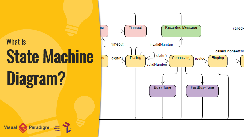
The behavior of an entity is not only a direct consequence of its inputs, but it also depends on its preceding state. The past history of an entity can best be modeled by a finite state machine diagram or traditionally called automata. UML State Machine Diagrams (or sometimes referred to as state diagram, state machine or state chart) show the different states of an entity. State machine diagrams can also show how an entity responds to various events by changing from one state to another. State machine diagram is a UML diagram used to model the dynamic nature of a system.

Are you looking for a Free UML tool for learning UML faster, easier and quicker? Visual Paradigm Community Edition is a UML software that supports all UML diagram types. It is an international award-winning UML modeler, and yet it is easy-to-use, intuitive & completely free.
Free DownloadState machine diagram typically are used to describe state-dependent behavior for an object. An object responds differently to the same event depending on what state it is in. State machine diagrams are usually applied to objects but can be applied to any element that has behavior to other entities such as: actors, use cases, methods, subsystems systems and etc. and they are typically used in conjunction with interaction diagrams (usually sequence diagrams).
For example:
Consider you have $100,000 in a bank account. The behavior of the withdraw function would be: balance := balance - withdrawAmount; provided that the balance after the withdrawal is not less than $0; this is true regardless of how many times you have withdrawn money from the bank. In such situations, the withdrawals do not affect the abstraction of the attribute values, and hence the gross behavior of the object remains unchanged.
However, if the account balance would become negative after a withdrawal, the behavior of the withdraw function would be quite different. This is because the state of the bank account is changed from positive to negative; in technical jargon, a transition from the positive state to the negative state is fired.
The abstraction of the attribute value is a property of the system, rather than a globally applicable rule. For example, if the bank changes the business rule to allow the bank balance to be overdrawn by 2000 dollars, the state of the bank account will be redefined with condition that the balance after withdrawal must not be less than $2000 in deficit.
Note That:
Rumbaugh defines that:
"A state is an abstraction of the attribute values and links of an object. Sets of values are grouped together into a state according to properties that affect the gross behavior of the object."

There are several characteristics of states in general, regardless of their types:
A state is a constraint or a situation in the life cycle of an object, in which a constraint holds, the object executes an activity or waits for an event.
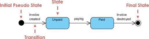
A state machine diagram is a graph consisting of:
Example:

Example:

An event signature is described as Event-name (comma-separated-parameter-list). Events appear in the internal transition compartment of a state or on a transition between states. An event may be one of four types:
Transition lines depict the movement from one state to another. Each transition line is labeled with the event that causes the transition.
Action is an executable atomic computation, which includes operation calls, the creation or destruction of another object, or the sending of a signal to an object. An action is associated with transitions and during which an action is not interruptible - e.g., entry, exit
Activity is associated with states, which is a non-atomic or ongoing computation. Activity may run to completion or continue indefinitely. An Activity will be terminated by an event that causes a transition from the state in which the activity is defined
Entry and Exit actions specified in the state. It must be true for every entry / exit occurrence. If not, then you must use actions on the individual transition arcs
This example illustrates a state machine diagram derived from a Class - "BookCopy":

Note:
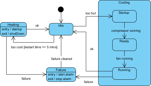
A simple state is one which has no substructure. A state which has substates (nested states) is called a composite state. Substates may be nested to any level. A nested state machine may have at most one initial state and one final state. Substates are used to simplify complex flat state machines by showing that some states are only possible within a particular context (the enclosing state).
Substate Example - Heater
State Machine Diagrams are often used for deriving testing cases, here is a list of possible test ideas:
Unless otherwise specified, when a transition enters a composite state, the action of the nested state machine starts over again at the initial state (unless the transition targets a substate directly). History states allow the state machine to re-enter the last substate that was active prior to leaving the composite state. An example of history state usage is presented in the figure below.

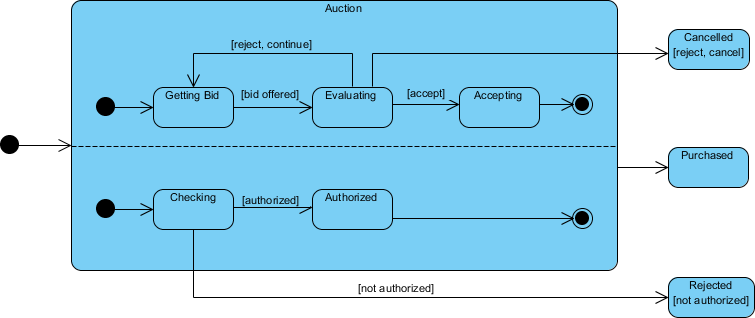
As mentioned above, states in state machine diagrams can be nested. Related states can be grouped together into a single composite state. Nesting states inside others is necessary when an activity involves concurrent sub-activities. The following state machine diagram models an auction with two concurrent substates: processing the bid and authorizing the payment limit.
Concurrent State Machine Diagram Example - Auction Process
In this example, the state machine first entering the Auction requires a fork at the start into two separate start threads. Each substate has an exit state to mark the end of the thread. Unless there is an abnormal exit (Canceled or Rejected), the exit from the composite state occurs when both substates have exited.
You've learned what a State Machine Diagram is and how to draw a State Machine Diagram. It's time to draw a State Machine Diagram of your own. Get Visual Paradigm Community Edition, a free UML software, and create your own State Machine Diagram with the free State Machine Diagram tool. It's easy-to-use and intuitive.
Free Download