Create UML models in a snap with an award-winning UML software.

Capture functional requirements with UML use case diagram tool. Each use case in a use case diagram represents a high level business goal that yields a measurable result of business values. (UML) Actors are connected with use cases to represent the roles that interact with the functions.

The UML modeling tool lets you model the structure of system by modeling its classes, their attributes and operations in a UML class diagram. UML class diagram is a blueprint of the classes (code level) required to build a software system. Programmers implement a software system with the help of both the class diagram and the class specification.

Visualize the interactions between users, systems and sub-systems over time through message passing between objects or roles. If class diagram represents the skeleton of classes by showing their attributes and methods, UML sequence diagram complete the classes by representing the programming logic to be filled in methods' body.

Collaboration between objects in runtime can be modeled in the UML tool, with a UML communication diagram. In a communication diagram, objects, called lifelines, are connected to represent the need of communication during the execution of an interaction. Messages can be added on top of the connectors to list the calls made from and to those lifelines.

Use UML activity diagram, a flowchart-based diagram to model the flow of control. Partition actions according to the type of participant involved.

State machine diagram is a critical design model for event-driven systems. Well-designed state machine shows accurately the essential states of objects as well as the triggers of state change, which facilitates the development of error-free state machine.

Components diagrams are used to model the structure of systems by showing how little parts of the system gear up in forming a bigger part, or forming the entire software systems.

Models the physical deployment of software components with UML deployment diagram. In deployment diagram, hardware components (e.g. web server, mail server, application server) are presented as nodes, with the software components that run inside the hardware components presented as artifacts.

Arrange and organize model for large-scale project with package diagrams. Package diagram is also good in visualizing structure and dependency between sub-systems or modules.

View a snapshot of instances of classifiers in UML class diagrams. Similar to class diagrams, object diagrams show the static design of a system from a prototypical perspective.

Visualize the internal structure of a class or collaboration with UML composite structure diagram. Model a system from a micro point-of-view using UML composite structure diagram.

Timing diagrams model the behavior of objects throughout a given period of time. It is a commonly used UML tool for designing real-time and distributed systems. Just drag to move a time unit back and forth. Have a timing frame updated automatically according to your change.

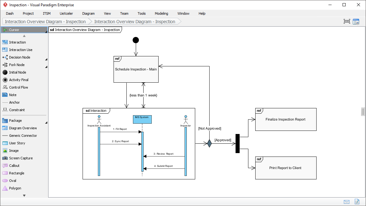
View the sequence of interactions with UML interaction overview diagram. Interaction overview diagram helps represent complex scenario that involve multiple interactions presented as multiple UML sequence diagrams.
A visual way to define stereotypes to use in your project. Draw stereotypes, define their tags and their inter-relationships like generalizations and associations. Specify formatting options like background color and icons.


Make internal links between different kinds of project artifacts. Those references work both in Visual Paradigm and in any document and Web contents generated from your design.
Maintain reference between software design and the business documents to help find out why a design decision was made.
Glance over a design. The tiny marker that appear in shapes' body indicates that the shapes have references added.
Insert model element references to rich text description. The referenced model elements will be linked and highlighted.
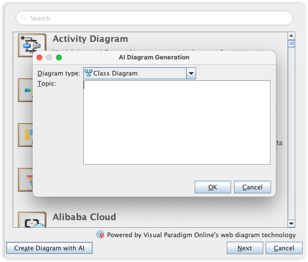
Visual Paradigm's UML toolset is the industry standard for software modeling, offering the full range of diagrams needed to bridge the gap between requirements and implementation. We are now elevating the entire modeling experience by integrating comprehensive UML support into our AI Diagram Generator, enabling you to visualize system behavior and structure with unprecedented speed.
This capability allows you to instantly generate a wide array of UML diagrams-including Use Case, Class, Sequence, State Machine, Requirement, and Object Diagrams-from a simple textual description. By leveraging AI to interpret your system requirements, the tool automatically maps out the necessary entities, relationships, and interactions, allowing you to move directly to design validation and architectural refinement instead of starting from a blank canvas.
Learn more