Importing Visio drawing
You may have drew diagrams in Visio. You can now import your previous work through the import feature.
- Save your Visio drawing as a .vdx or .vsdx file .
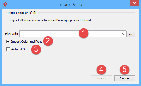
- To import a Visio drawing into Visual Paradigm, select Project > Import > Visio... in the toolbar of Visual Paradigm.
- Specify the file path of the Visio drawing.
- Click OK to start importing. This popup another Import Visio window. As the model structure is different among Visio and Visual Paradigm, this dialog enables users to resolve inconsistency between Visio and Visual Paradigm.
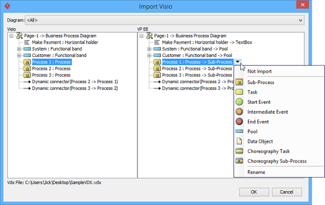
The Import Visio window
The left hand side of the window represents the structure of Visio drawing, while the right hand side represents the expected outcome in Visual Paradigm through importing. Users can perform the following actions in this window.
Action Description and steps Not to import a shape Click on the button beside the shape node and select Not Import in the popup menu. Rename a shape when importing Click on the button beside the shape node and select Rename in the popup menu. Then, enter the new name of shape and press the Enter key to confirm renaming/. Reset the shape to another type Click on the button beside the shape node and select an appropriate shape type to reset to. Description of available import options on individual shape - Click OK when the import is configured. The drawings can then be accessible in the Diagram Navigator. You can then double click on the diagram node to open the diagram.
An overview of Import Visio window
 |
| An overview of Import Visio window |
|
||||||||||||||||||
| Description of Import Visio window |
Related Resources
The following resources may help you to learn more about the topic discussed in this page.
| Chapter 6. Importing Visio drawing | Table of Contents | Chapter 7. Importing Rational Rose model |