Data modeling is the process of producing a diagram (i.e. ERD) of relationships between various types of information that are to be stored in a database that helps us to think systematically about the key data points to be stored and retrieved, and how they should be grouped and related, is what the
A data model describes information in a systematic way that allows it to be stored and retrieved efficiently in a Relational Database System which can be thought of as a way of translating the logic of accurately describing things in the real world and the relationships between them into rules that can be followed and enforced by computer code. One of the goals of data modeling is to create the most efficient method of storing information while still providing for complete access and reporting.
An Entity Relationship Diagram (ERD), initially proposed by Peter Chen in 1976, is a visual representation of data modeling using symbols and notation that describes how these data are related to each other. It can directly be used by database developers as the blueprint for implementing data in specific software applications. Any object, such as entities, attributes of an entity, sets of relationship and other attributes of relationship can be characterized with the help of the ER diagram.
An ERD allows the readers to understand the relationship among different fields in an effective manner. Symbols are utilized to represent information effectively and they also help in comprehending the working of the database. ER diagrams constitute a very useful data modeling technique which includes:
ER modeling is a top-down structure to database design that begins with identifying the important data called entities and relationships in combination with the data that must be characterized in the model. Then database model designers can add more details such as the information they want to hold about the entities and relationships which are the attributes and any constraints on the entities, relationships, and attributes. ER modeling is an important technique for any database designer to master and forms the basis of the methodology.
Entity type: It is a group of objects with the same properties that are identified by the enterprise as having an independent existence. The basic concept of the ER model is the entity type that is used to represent a group of ‘objects’ in the ‘real world’ with the same properties. An entity type has an independent existence within a database.
Attributes are the properties of entities that are represented using ellipse-shaped figures. Every elliptical figure represents one attribute and is directly connected to its entity (which is represented as a rectangle).
A relationship type is a set of associations between one or more participating entity types. Each relationship type is given a name that describes its function. There are four types of relationships. These are:
Here are some examples:
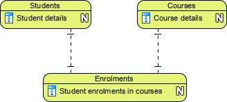
One to one
![]()
One to many
![]()
Many to many
![]()
One to zero or many
![]()
ER Modeling recognizes three different levels of abstraction at which models are developed. The three levels of data modeling, conceptual data model, logical data model, and physical data model.
Conceptual, logical and physical models or ERD are three different ways of modeling data in a domain. While they all contain entities and relationships, they differ in the purposes they are created for and audiences they are meant to target. A general understanding of the three models is that business analyst uses the conceptual and logical model for modeling the data required and produced by system from a business angle, while database designer refines the early design to produce the physical model for presenting physical database structure ready for database construction.
Here we compare these three types of data models. The table below compares the different features:
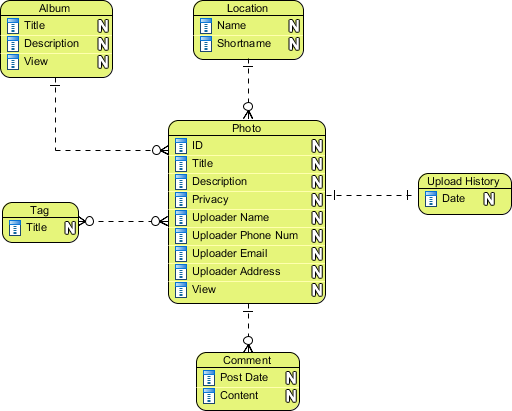
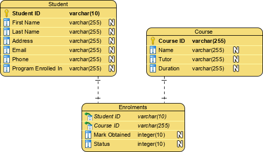
Conceptual: A conceptual model should be focused on things related to the business and its requirements. It gathered from business requirements. Entities and relationships modeled in such ERD are defined around the business’s needs. The need for satisfying the database design is not considered yet. Conceptual ERD is the simplest model among all.
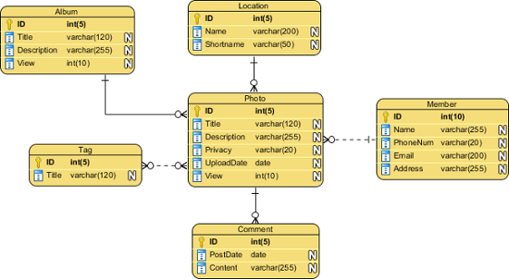
Logical: A logical model should be focused on the design of data about those things but without reference to a particular physical implementation. It is more complex than a conceptual model in that column types are set. Note that the setting of column types is optional and if you do that, you should be doing that to aid business analysis. It has nothing to do with database creation yet.
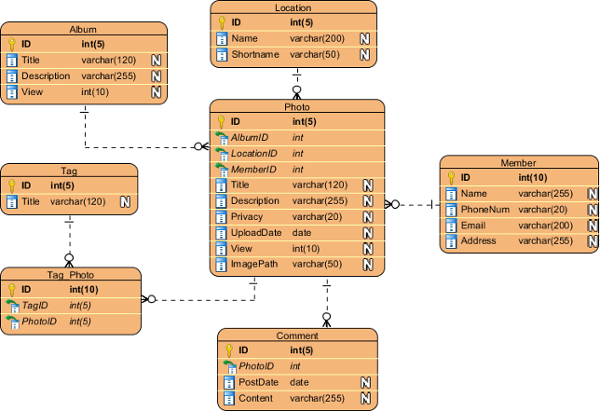
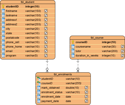
Physical: A physical model should be focused on how logical data should be represented and stored in a particular physical database. It represents the actual design blueprint of a relational database. It represents how data should be structured and related in a specific DBMS so it is important to consider the convention and restriction of the DBMS you use when you are designing a physical ERD. This means that accurate use of data type is needed for entity columns and the use of reserved words has to be avoided in naming entities and columns. Besides, database designers may also add primary keys, foreign keys, and constraints to the design.
A general understanding to the three data models is that business analyst uses a conceptual and logical model to model the business objects exist in the system, while database designer or database engineer elaborates the conceptual and logical ER model to produce the physical model that presents the physical database structure ready for database creation. Here is another example for illustrating the 3 different levels of the data model.
While all the three levels of an ER model contain entities with attributes and relationships, they differ in the purposes they are created for and the audiences they are meant to target. The table below shows the difference between the three data models.
| ERD features | Conceptual | Logical | Physical |
| Entity (Name) | Yes | Yes | Yes |
| Relationship | Yes | Yes | Yes |
| Columns | Yes | Yes | |
| Column’s Types | Optional | Yes | |
| Primary Key | Yes | ||
| Foreign Key | Yes |