A sequence diagram is a kind of behavior diagram that presents a dynamic view of the use case, a requirement, or a system, a view that expresses sequences of behaviors and event occurrences over time. You can use elements called lifelines to model the participants in system behavior and then use messages between lifelines to model interactions among those participants. Interaction uses to let you model behavioral decomposition among a set of interactions. You can also specify time constraints and duration constraints on interactions.
SysML includes the Sequence Diagram only and excludes the Interaction Overview Diagram and Communication Diagram, which were considered to offer significantly overlapping functionality without adding the significant capability for system modeling applications. The Timing Diagram is also excluded due to concerns about its maturity and suitability for systems engineering needs
A use case is a collection of interactions between external actors and a system. A use case is “the specification of a sequence of actions, including variants, that a system (or entity) can perform, interacting with actors of the system.
A scenario is one path or flows through a use case that describes a sequence of events that occurs during one particular execution of a system which is often represented by a sequence diagram.
User requirements are captured as use cases that are refined into scenarios. A use case is a collection of interactions between external actors and a system. Typically each use case includes a primary scenario (or main course of events) and zero or more secondary scenarios that are alternative courses of events to the primary scenario. It is often useful to visualize use case scenarios for the following reasons:
Sequence Diagram is an interaction diagram that details how operations are carried out — what messages are sent and when. Sequence diagrams are organized according to time. The time progresses as you go down the page. The objects involved in the operation are listed from left to right according to when they take part in the message sequence.
Sequence Diagrams show elements as they interact over time and they are organized according to object (horizontally) and time (vertically):
Object (lifeline) Dimension
An object lifeline represents the existence of an object over some time. Objects that exist throughout an interaction should appear at the top of the object dimension with their lifelines drawn parallel to the Time dimension. Objects that are created and destroyed dynamically (transient objects) have object lifelines that begin and end with a receipt of a message.
Time Dimension
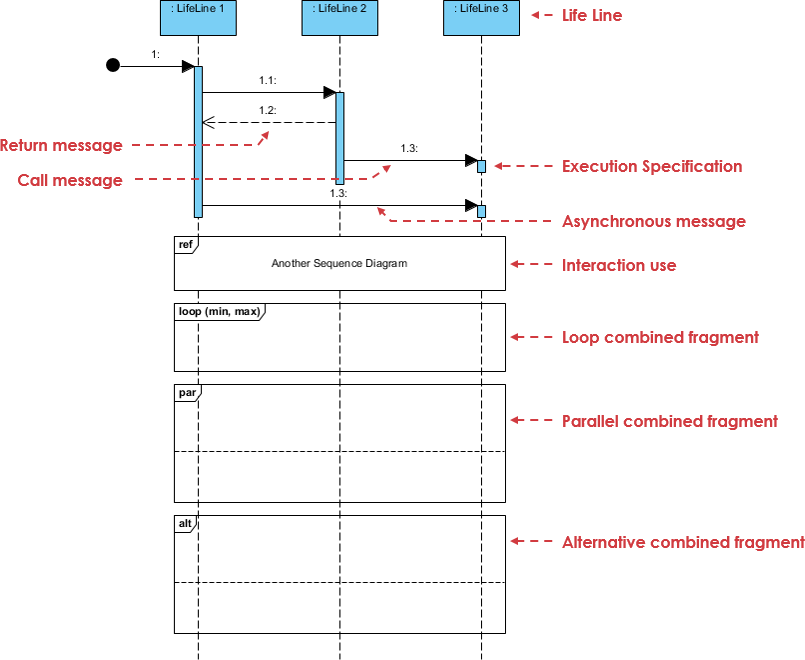
The Example below is a generic sequence diagram showing the sequence of messages interacted between the objects with frames and message constraints.
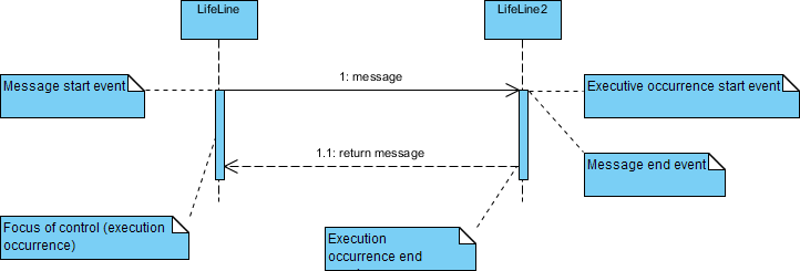
A focus of control, also known as the Activation bar, illustrates the period an object is acting. Actions can either be performed directly by an object or through a subordinate object to which it has sent messages.
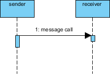
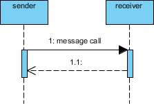
Messages specify communication from one object to another, with an expectation that an activity will be performed by the recipient object.
Messages depict the invocation of operations are shown horizontally. They are drawn from the sender to the receiver. Ordering is indicated by the vertical position, with the first message shown at the top of the diagram, and the last message shown at the bottom. As a result, sequence numbers are optional.
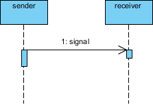
The line type and arrowhead type indicates the type of message is used:
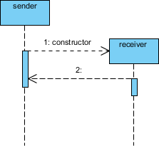
Participants do not necessarily live for the entire duration of a sequence diagram’s interaction. Participants can be created and destroyed according to the messages that are being passed.
A constructor message creates its receiver. The sender that already exists at the start of the interaction is placed at the top of the diagram. Targets that are created during the interaction by a constructor call are automatically placed further down the diagram.
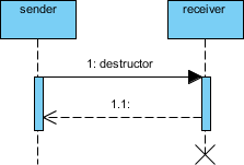
A destructor message destroys its receiver. There are other ways to indicate that a target is destroyed during an interaction. Only when a target’s destruction is set to ‘after destructor’ do you have to use a destructor.
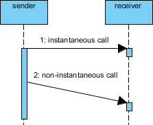
Messages are often considered to be instantaneous, thus, the time it takes to arrive at the receiver is negligible. The messages are drawn as a horizontal arrow. To indicate that it takes a certain while before the receiver receives a message, a slanted arrow is used.
The sequence diagram example below illustrates how you can represent objects, object lifelines, the focus of control, links, and messages in the context of a Sequence diagram.
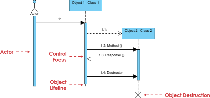
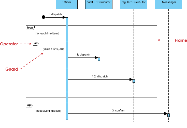
Diagram frames explicitly define the boundary of a diagram whereas combined fragment frames encompass portions of a diagram or provide references to other diagrams or method definitions.
A Sequence Frame Notation is a graphical notation used in a UML Sequence Diagram to provide a boundary to enclose all messages and lifelines of a communication sequence.
A Sequence Frame Notation is drawn as a large rectangle with a pentagon at the top left corner. “sd” followed by the sequence name are written in the pentagon.
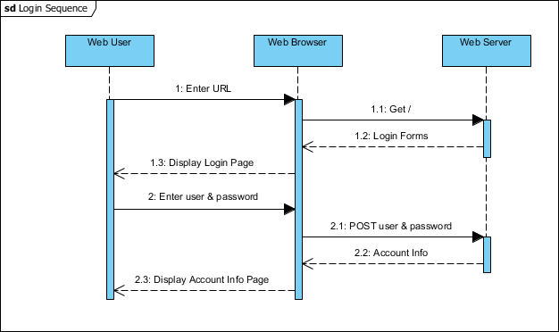
For example, a communication message interchanges between a user, a Web browser and a Web server to perform a user login process can be described as a communication message sequence with sequence frame.
You can use sequence Fragments to add additional semantics to a sequence diagram.
A common issue with sequence diagrams is how to show looping and conditional behavior. The first thing to point out is that this isn’t what sequence diagrams are good at. If you want to show control structures like this, you are better off with an activity diagram or indeed with code itself. Treat sequence diagrams as a visualization of how objects interact rather than as a way of modeling control logic.
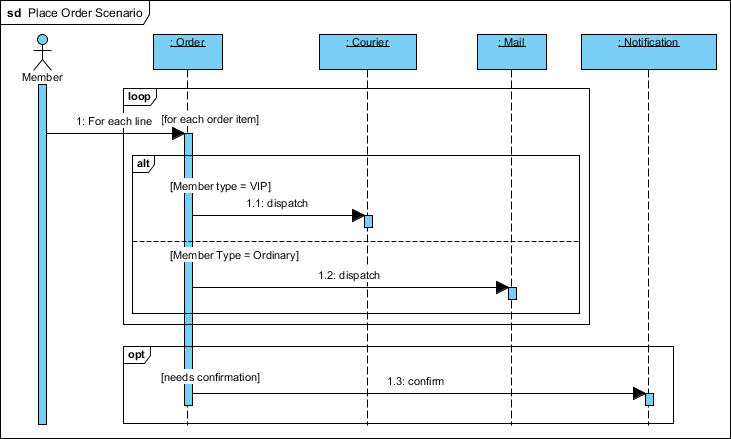
If you still prefer to model this in a sequence diagram, here’s the notation to use. Both loop and conditional use interaction frames, which are ways of marking off a piece of a sequence diagram. The sequence diagram example below shows a simple algorithm based on the following pseudocode:
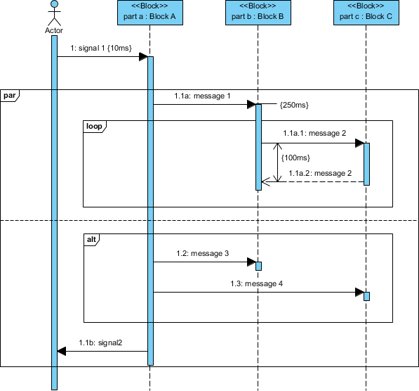
| alt | Alternative multiple fragments: only the one whose condition is true will execute. |
| opt | Optional: the fragment executes only if the supplied condition is true. Equivalent to an alt only with one trace. |
| par | Parallel: each fragment is run in parallel. |
| loop | Loop: the fragment may execute multiple times, and the guard indicates the basis of iteration. |
| region | Critical region: the fragment can have only one thread executing it at once. |
| neg | Negative: the fragment shows an invalid interaction. |
| ref | Reference: refers to an interaction defined in another diagram. The frame is drawn to cover the lifelines involved in the interaction. You can define parameters and return value. |
| sd | Sequence diagram: used to surround an entire sequence diagram. |
A member of a ship who would like to place an order online. The item ordered will be sent to the member either send by courier or by ordinary mail depending on the member status (VIP, Ordinary membership). Optionally, the shop will send the member a confirmation notice if the member opted for the notification option in the order.