|
 |
|
|
Composite Structure diagram |
|
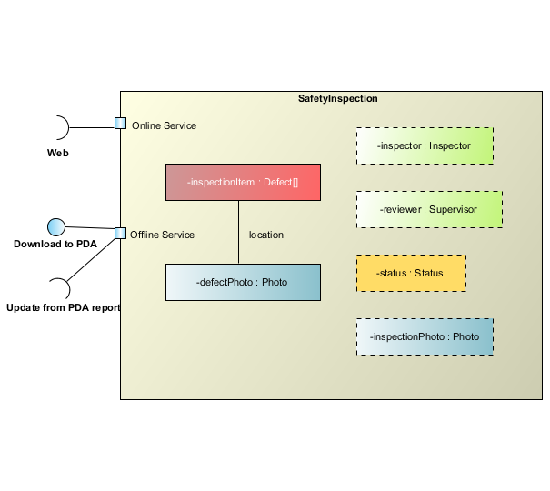
Composite Structure Diagram is one of the new artifacts added to UML 2.0. It shows the internal structure (including parts and connectors) of a structured classifier or collaboration. Visual Paradigm provides full support to the Composite Structure Diagram, includes modeling the internal structure of the objects and functionality.
|
|
|
Use case diagram
|
Class diagram
|
Sequence diagram
|
Communication diagram
|
State machine diagram
|
Activity diagram
|
Component diagram
|
Deployment diagram
|
Package diagram
|
Object diagram
|
Composite structure diagram
|
Timing diagram
|
Interaction overview diagram
|
|
|
|
|
Composite Structure diagram |
|
|
|
Notation
 | | Aggregation (Shared association) |  | | Association (Without aggregation) | |  | | Class |  | | Collaboration | |  | | Collaboration Use |  | | Connector | |  | | Composition (Composite association) |  | | Constraint | |  | | Dependency |  | | Generalization | |  | | Interface |  | | Note | |  | | Occurrence |  | | Part | |  | | Port |  | | Property | |  | | Realization |  | | Represents | |
| DefinitionComposite structure diagram visualizes the internal structure of a class or collaboration. Composite structure diagram is a kind of component diagram mainly used in modeling a system at micro point-of-view. |
|
| |
Aggregation (Shared association) | | 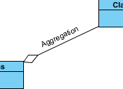 | | Definition | | A kind of association that has one of its end marked shared as kind of aggregation, meaning that it has a shared aggregation. |
| | Properties | | | Name | The name of aggregation. | | Visibility | Determines where the aggregation appears within different namespaces within the overall model, and its accessibility. | | Association End From | The source of aggregation. | | Association End To | The target of aggregation. | | Documentation | Description of aggregation. | | Abstract | If true, the aggregation does not provide a complete declaration and can typically not be instantiated. An abstract aggregation is intended to be used by other aggregations. | | Leaf | Indicates whether it is possible to further specialize an aggregation. If the value is true, then it is not possible to further specialize the aggregation. | | Derived | Specifies whether the aggregation is derived from other model elements such as other aggregations or constraints. |
|
|
|
| | | Association (Without aggregation) | | 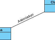 | | Definition | An association specifies a semantic relationship that can occur between typed instances. It has at least two ends represented by properties, each of which is connected to the type of the end. More than one end of the association may have the same type.
An end property of an association that is owned by an end class or that is a navigable owned end of the association indicates that the association is navigable from the opposite ends; otherwise, the association is not navigable from the opposite ends. |
| | Properties | | | Name | The name of association. | | Visibility | Determines where the association appears within different namespaces within the overall model, and its accessibility. | | Association End From | The source of association. | | Association End To | The target of association. | | Documentation | Description of association. | | Abstract | If true, the association does not provide a complete declaration and can typically not be instantiated. An abstract association is intended to be used by other associations. | | Leaf | Indicates whether it is possible to further specialize an association. If the value is true, then it is not possible to further specialize the association. | | Derived | Specifies whether the association is derived from other model elements such as other associations or constraints. |
|
|
|
| | | Class | |  | | Definition | | A class describes a set of objects that share the same specifications of features, constraints, and semantics. Class is a kind of classifier whose features are attributes and operations. Attributes of a class are represented by instances of Property that are owned by the class. Some of these attributes may represent the navigable ends of binary associations. |
| | Properties | | | Name | The name of class. | | Parent | The model element that owns the class. | | Visibility | Determines where the class appears within different namespaces within the overall model, and its accessibility. | | Documentation | Description of class. | | Abstract | If true, the class does not provide a complete declaration and can typically not be instantiated. An abstract class is intended to be used by other classes. | | Leaf | Indicates whether it is possible to further specialize a class. If the value is true, then it is not possible to further specialize the class. | | Root | Indicates whether the class has no ancestors. (true for no ancestors) | | Active | Determines whether an object specified by this class is active or not. If true, then the owning class is referred to as an active class. If false, then such a class is referred to as a passive class. | | Business model | Set it to make the class become a "business class" | | Attributes | Refers to all of the Properties that are direct (i.e., not inherited or imported) attributes of the class. | | Operations | An operation is a behavioral feature of a class that specifies the name, type, parameters, and constraints for invoking an associated behavior. Operations here refers to the operations owned by the class. | | Template Parameters | A TemplateableElement that has a template signature is a specification of a template. A template is a parameterized element that can be used to generate other model elements using TemplateBinding relationships. The template parameters for the template signature specify the formal parameters that will be substituted by actual parameters (or the default) in a binding.
A template parameter is defined in the namespace of the template, but the template parameter represents a model element that is defined in the context of the binding.
A templateable element can be bound to other templates. This is represented by the bound element having bindings to the template signatures of the target templates. In a canonical model a bound element does not explicitly contain the model elements implied by expanding the templates it binds to, since those expansions are regarded as derived. The semantics and well-formedness rules for the bound element must be evaluated as if the bindings were expanded with the substitutions of actual elements for formal parameters | | Class Code Details | Properties of class in implementation (code) level. Settings in this page is programming language specific, and will affect the code being generated. | | Java Annotations | A Java annotation is a metadata that can be added to Java source code for annotation purposes. | | ORM Query | Available only to ORM Persistable class, ORM Query lets you define the ORM Qualifiers and named queries of the class. |
|
|
|
| | | Collaboration | |  | | Definition | A collaboration is represented as a kind of classifier and defines a set of cooperating entities to be played by instances (its roles), as well as a set of connectors that define communication paths between the participating instances. The cooperating entities are the properties of the collaboration.
A collaboration specifies a view (or projection) of a set of cooperating classifiers. It describes the required links between instances that play the roles of the collaboration, as well as the features required of the classifiers that specify the participating instances. Several collaborations may describe different projections of the same set of classifiers. |
| | Properties | | | Name | The name of collaboration. | | Visibility | Determines where the collaboration appears within different namespaces within the overall model, and its accessibility. | | Documentation | Description of collaboration. |
|
|
|
| | | Collaboration Use | |  | | Definition | | A collaboration use represents the application of the pattern described by a collaboration to a specific situation involving specific classes or instances playing the roles of the collaboration. |
| | Properties | | | Name | The name of collaboration use. | | Visibility | Determines where the collaboration use appears within different namespaces within the overall model, and its accessibility. | | Type | The collaboration that is used in this occurrence. The collaboration defines the cooperation between its roles that are mapped to properties of the classifier owning the collaboration use. | | Documentation | Description of collaboration use. |
|
|
|
| | | Connector | |  | | Definition | | Specifies a link that enables communication between two or more instances. This link may be an instance of an association, or it may represent the possibility of the instances being able to communicate because their identities are known by virtue of being passed in as parameters, held in variables or slots, or because the communicating instances are the same instance. The link may be realized by something as simple as a pointer or by something as complex as a network connection. In contrast to associations, which specify links between any instance of the associated classifiers, connectors specify links between instances playing the connected parts only. |
| | Properties | | | Name | The name of connector. | | From End | The source of connector. | | To End | The target of connector. | | Visibility | Determines where the connector appears within different namespaces within the overall model, and its accessibility. | | Type | An optional association that specifies the link corresponding to this connector. | | Documentation | Description of connector. | | Leaf | Indicates whether it is possible to further specialize a connector. If the value is true, then it is not possible to further specialize the connector. | | Static | Specifies whether this feature characterizes individual instances classified by the classifier (false) or the classifier itself (true). | | Redefined Connectors | A connector may be redefined when its containing classifier is specialized. The redefining connector may have a type that specializes the type of the redefined connector. The types of the connector ends of the redefining connector may specialize the types of the connector ends of the redefined connector. The properties of the connector ends of the redefining connector may be replaced. |
|
|
|
| | | Composition (Composite association) | | 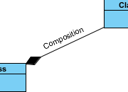 | | Definition | | An association may represent a composite aggregation (i.e., a whole/part relationship). Only binary associations can be aggregations. Composite aggregation is a strong form of aggregation that requires a part instance be included in at most one composite at a time. If a composite is deleted, all of its parts are normally deleted with it. Note that a part can (where allowed) be removed from a composite before the composite is deleted, and thus not be deleted as part of the composite. Compositions may be linked in a directed acyclic graph with transitive deletion characteristics; that is, deleting an element in one part of the graph will also result in the deletion of all elements of the subgraph below that element. Composition is represented by the isComposite attribute on the part end of the association being set to true. |
| | Properties | | | Name | The name of composition. | | Visibility | Determines where the association appears within different namespaces within the overall model, and its accessibility. | | Association End From | The source of association. | | Association End To | The target of association. | | Documentation | Description of association. | | Abstract | If true, the composition does not provide a complete declaration and can typically not be instantiated. An abstract composition is intended to be used by other compositions. | | Leaf | Indicates whether it is possible to further specialize a composition. If the value is true, then it is not possible to further specialize the composition. | | Derived | Specifies whether the composition is derived from other model elements such as other compositions or constraints. |
|
|
|
| | | Constraint | | 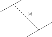 | | Definition | | A condition or restriction expressed in natural language text or in a machine readable language for the purpose of declaring some of the semantics of an element. |
| | Properties | | | Name | The name of constraint. It is optional and is commonly omitted. | | Expression | The condition that must be true when evaluated in order for the constraint to be satisfied. | | Documentation | Description of constraint. |
|
|
|
| | | Dependency | | 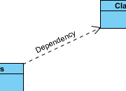 | | Definition | | A dependency is a relationship that signifies that a single or a set of model elements requires other model elements for their specification or implementation. This means that the complete semantics of the depending elements is either semantically or structurally dependent on the definition of the supplier element(s). |
| | Properties | | | Name | The name of dependency. | | Supplier | The element(s) independent of the client element(s), in the same respect and the same dependency relationship. In some directed dependency relationships (such as Refinement Abstractions), a common convention in the domain of class-based OO software is to put the more abstract element in this role. Despite this convention, users of UML may stipulate a sense of dependency suitable for their domain, which makes a more abstract element dependent on that which is more specific. | | Client | The element(s) dependent on the supplier element(s). In some cases (such as a Trace Abstraction) the assignment of direction (that is, the designation of the client element) is at the discretion of the modeler, and is a stipulation. | | Visibility | Determines where the dependency appears within different namespaces within the overall model, and its accessibility. | | Documentation | Description of dependency. |
|
|
|
| | | Generalization | | 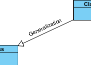 | | Definition | | A generalization is a taxonomic relationship between a more general classifier and a more specific classifier. Each instance of the specific classifier is also an indirect instance of the general classifier. Thus, the specific classifier inherits the features of the more general classifier. |
| | Properties | | | Name | The name of generalization. | | General | References the general classifier in the Generalization relationship. | | Specific | References the specializing classifier in the Generalization relationship. | | Visibility | Determines where the generalization relationship appears within different namespaces within the overall model, and its accessibility. | | Documentation | Description of generalization relationship. | | Substitutable | Indicates whether the specific classifier can be used wherever the general classifier can be used. If true, the execution traces of the specific classifier will be a superset of the execution traces of the general classifier. |
|
|
|
| | | Interface | |  | | Definition | An interface is a kind of classifier that represents a declaration of a set of coherent public features and obligations. An interface specifies a contract; any instance of a classifier that realizes the interface must fulfill that contract. The obligations that may be associated with an interface are in the form of various kinds of constraints (such as pre- and postconditions) or protocol specifications, which may impose ordering restrictions on interactions through the interface.
Since interfaces are declarations, they are not instantiable. Instead, an interface specification is implemented by an instance of an instantiable classifier, which means that the instantiable classifier presents a public facade that conforms to the interface specification. Note that a given classifier may implement more than one interface and that an interface may be implemented by a number of different classifiers. |
| | Properties | | | Name | The name of interface. | | Parent | The model element that owns the interface. | | Visibility | Determines where the interface appears within different namespaces within the overall model, and its accessibility. | | Documentation | Description of interface. | | Abstract | If true, the class does not provide a complete declaration and can typically not be instantiated. An abstract class is intended to be used by other classes. | | Leaf | Indicates whether it is possible to further specialize a class. If the value is true, then it is not possible to further specialize the class. | | Root | Indicates whether the class has no ancestors. (true for no ancestors) | | Active | Determines whether an object specified by this class is active or not. If true, then the owning class is referred to as an active class. If false, then such a class is referred to as a passive class. | | Business model | Set it to make the class become a "business class" | | Attributes | Refers to all of the Properties that are direct (i.e., not inherited or imported) attributes of the class. | | Operations | An operation is a behavioral feature of a class that specifies the name, type, parameters, and constraints for invoking an associated behavior. Operations here refers to the operations owned by the class. | | Template Parameters | A TemplateableElement that has a template signature is a specification of a template. A template is a parameterized element that can be used to generate other model elements using TemplateBinding relationships. The template parameters for the template signature specify the formal parameters that will be substituted by actual parameters (or the default) in a binding.
A template parameter is defined in the namespace of the template, but the template parameter represents a model element that is defined in the context of the binding.
A templateable element can be bound to other templates. This is represented by the bound element having bindings to the template signatures of the target templates. In a canonical model a bound element does not explicitly contain the model elements implied by expanding the templates it binds to, since those expansions are regarded as derived. The semantics and well-formedness rules for the bound element must be evaluated as if the bindings were expanded with the substitutions of actual elements for formal parameters | | Class Code Details | Properties of class in implementation (code) level. Settings in this page is programming language specific, and will affect the code being generated. | | Java Annotations | A Java annotation is a metadata that can be added to Java source code for annotation purposes. |
|
|
|
| | | Note | | 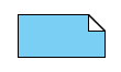 | | Definition | | A note (comment) gives the ability to attach various remarks to elements. A comment carries no semantic force, but may contain information that is useful to a modeler. |
| | Properties | | | Name | The name of note. | | Documentation | Specifies a string that is the comment. |
|
|
|
| | | Occurrence | | 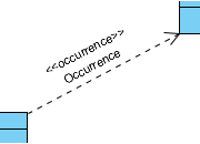 | | Definition | | A kind of dependency which shows a occurrence relationship between two elements. |
| | Properties | | | Name | The name of occurrence. | | Supplier | The element(s) independent of the client element(s), in the same respect and the same occurrence relationship. In some directed occurrence relationships (such as Refinement Abstractions), a common convention in the domain of class-based OO software is to put the more abstract element in this role. Despite this convention, users of UML may stipulate a sense of occurrence suitable for their domain, which makes a more abstract element dependent on that which is more specific. | | Client | The element(s) dependent on the supplier element(s). In some cases (such as a Trace Abstraction) the assignment of direction (that is, the designation of the client element) is at the discretion of the modeler, and is a stipulation. | | Visibility | Determines where the occurrence appears within different namespaces within the overall model, and its accessibility. | | Documentation | Description of occurrence. |
|
|
|
| | | Part | | 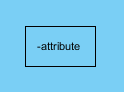 | | Definition | A part represents a set of instances that are owned by a containing classifier instance.
When an instance of the containing classifier is created, a set of instances corresponding to its parts may be created either immediately or at some later time. These instances are instances of the classifier typing the part. A part specifies that a set of instances may exist; this set of instances is a subset of the total set of instances specified by the classifier typing the part. |
| | Properties | | | Name | The name of part. | | Classifier | References the Class that owns the part. | | Initial Value | The default value of attribute when its classifier is initiated. | | Multiplicity | Specifies the allowable cardinalities for an instantiation of this part. | | Visibility | Determines where the part appears within different namespaces within the overall model, and its accessibility. | | Type | The DataType that owns this part | | Type Modifier | Indicates a modifier that applies to the part. | | Scope | Determines whether the part is an instance or classifier. | | Aggregation | Specifies the kind of aggregation that applies to the part. | | Documentation | Description of part. | | Derive | Specifies whether the part is derived, i.e., whether its value or values can be computed from other information. | | Setter | Specifies whether the part comes with a setter. This option is effective only for code generation. | | Getter | Specifies whether the part comes with a getter. This option is effective only for code generation. | | Abstract | If true, the part does not provide a complete declaration and can typically not be instantiated. An abstract part is intended to be used by other parts. | | Attribute Code Details | Properties of part in implementation (code) level. Settings in this page is programming language specific, and will affect the code being generated. |
|
|
|
| | | Port | |  | | Definition | | A port is a property of a classifier that specifies a distinct interaction point between that classifier and its environment or between the (behavior of the) classifier and its internal parts. Ports are connected to properties of the classifier by connectors through which requests can be made to invoke the behavioral features of a classifier. A Port may specify the services a classifier provides (offers) to its environment as well as the services that a classifier expects (requires) of its environment. |
| | Properties | | | Name | The name of port. | | Multiplicity | Specifies the allowable cardinalities for an instantiation of this port. | | Visibility | Determines where the port appears within different namespaces within the overall model, and its accessibility. | | Type | The DataType that owns this port | | Type Modifier | Indicates a modifier that applies to the port. | | Aggregation | Specifies the kind of aggregation that applies to the part. | | Default Value | A String that is evaluated to give a default value for the Property when an object of the owning Classifier is instantiated. | | Redefined Port | A port may be redefined when its containing classifier is specialized. The redefining port may have additional interfaces to those that are associated with the redefined port or it may replace an interface by one of its subtypes. | | Documentation | Description of port. | | Leaf | Indicates whether it is possible to further specialize a class. If the value is true, then it is not possible to further specialize the class. | | Static | Specifies whether this feature characterizes individual instances classified by the classifier (false) or the classifier itself (true). | | Read Only | If true, the attribute may only be read, and not written. | | Derive | Specifies whether the port is derived, i.e., whether its value or values can be computed from other information. | | Derived Union | Specifies whether the port is derived as the union of all of the ports that are constrained to subset it. | | Service | If true, indicates that this port is used to provide the published functionality of a classifier. If false, this port is used to implement the classifier but is not part of the essential externally-visible functionality of the classifier and can, therefore, be altered or deleted along with the internal implementation of the classifier and other properties that are considered part of its implementation. | | Behavior | Specifies whether requests arriving at this port are sent to the classifier behavior of this classifier. Such ports are referred to as behavior port. Any invocation of a behavioral feature targeted at a behavior port will be handled by the instance of the owning classifier itself, rather than by any instances that this classifier may contain. |
|
|
|
| | | Property | | 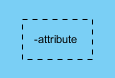 | | Definition | A property represents a set of instances that are owned by a containing classifier instance.
When an instance of the containing classifier is created, a set of instances corresponding to its properties may be created either immediately or at some later time. These instances are instances of the classifier typing the property. A property specifies that a set of instances may exist; this set of instances is a subset of the total set of instances specified by the classifier typing the property. |
| | Properties | | | Name | The name of property. | | Classifier | References the Class that owns the Property. | | Initial Value | The default value of attribute when its classifier is initiated. | | Multiplicity | Specifies the allowable cardinalities for an instantiation of this property. | | Visibility | Determines where the property appears within different namespaces within the overall model, and its accessibility. | | Type | The DataType that owns this Property | | Type Modifier | Indicates a modifier that applies to the property. | | Scope | Determines whether the property is an instance or classifier. | | Aggregation | Specifies the kind of aggregation that applies to the Property. | | Documentation | Description of property. | | Derive | Specifies whether the property is derived, i.e., whether its value or values can be computed from other information. | | Setter | Specifies whether the property comes with a setter. This option is effective only for code generation. | | Getter | Specifies whether the property comes with a getter. This option is effective only for code generation. | | Abstract | If true, the property does not provide a complete declaration and can typically not be instantiated. An abstract property is intended to be used by other properties. | | Attribute Code Details | Properties of property in implementation (code) level. Settings in this page is programming language specific, and will affect the code being generated. |
|
|
|
| | | Realization | | 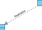 | | Definition | | Realization is a specialized abstraction relationship between two sets of model elements, one representing a specification (the supplier) and the other represents an implementation of the latter (the client). Realization can be used to model stepwise refinement, optimizations, transformations, templates, model synthesis, framework composition, etc. |
| | Properties | | | Name | The name of realization relationship. | | Supplier | The element(s) independent of the client element(s), in the same respect and the same dependency relationship. In some directed dependency relationships (such as Refinement Abstractions), a common convention in the domain of class-based OO software is to put the more abstract element in this role. Despite this convention, users of UML may stipulate a sense of dependency suitable for their domain, which makes a more abstract element dependent on that which is more specific. | | Client | The element(s) dependent on the supplier element(s). In some cases (such as a Trace Abstraction) the assignment of direction (that is, the designation of the client element) is at the discretion of the modeler, and is a stipulation. | | Visibility | Determines where the realization relationship appears within different namespaces within the overall model, and its accessibility. | | Mapping | A composition of an Expression that states the abstraction relationship between the supplier and the client. In some cases, such as Derivation, it is usually formal and unidirectional. In other cases, such as Trace, it is usually informal and bidirectional. The mapping expression is optional and may be omitted if the precise relationship between the elements is not specified. | | Documentation | Description of realization relationship. |
|
|
|
| | | Represents | |  | | Definition | | A kind of dependency which shows a represents relationship between two elements. |
| | Properties | | | Name | The name of represents. | | Supplier | The element(s) independent of the client element(s), in the same respect and the same represents relationship. In some directed represents relationships (such as Refinement Abstractions), a common convention in the domain of class-based OO software is to put the more abstract element in this role. Despite this convention, users of UML may stipulate a sense of represents suitable for their domain, which makes a more abstract element dependent on that which is more specific. | | Client | The element(s) dependent on the supplier element(s). In some cases (such as a Trace Abstraction) the assignment of direction (that is, the designation of the client element) is at the discretion of the modeler, and is a stipulation. | | Visibility | Determines where the represents appears within different namespaces within the overall model, and its accessibility. | | Documentation | Description of represents. |
|
|
|
|
| |
| Definition of notations is quoted from Object Management Group Unified Modeling Language (OMG UML) Superstructure Version 2.2 and former versions (for notations that do not exist anymore in latest specification). |
| |
|
Use case diagram
|
Class diagram
|
Sequence diagram
|
Communication diagram
|
State machine diagram
|
Activity diagram
|
Component diagram
|
Deployment diagram
|
Package diagram
|
Object diagram
|
Composite structure diagram
|
Timing diagram
|
Interaction overview diagram
|
|
|
|
|
 |
|