|
 |
|
|
Use case diagram |
|
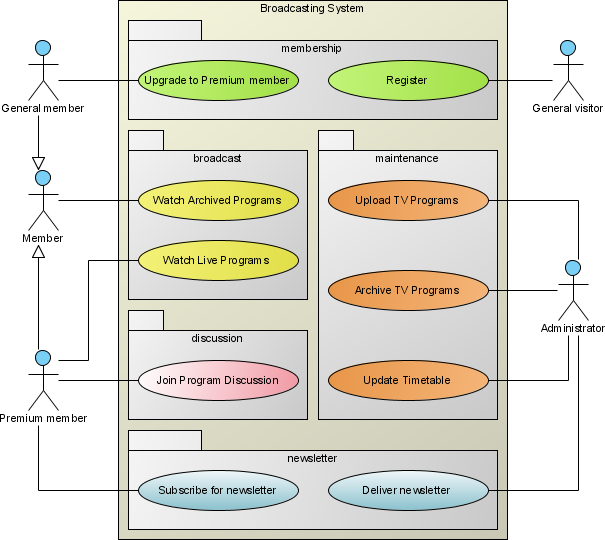
Creating Use Case Diagram for describing the behavior of the target system from an external point of view. Besides drawing the diagram, Visual Paradigm allows you to detail document the requirements through the Use Case Description. All these information can be output into HTML//PDF//MS Word formats.
|
|
|
Use case diagram
|
Class diagram
|
Sequence diagram
|
Communication diagram
|
State machine diagram
|
Activity diagram
|
Component diagram
|
Deployment diagram
|
Package diagram
|
Object diagram
|
Composite structure diagram
|
Timing diagram
|
Interaction overview diagram
|
|
|
|
|
Use case diagram |
|
|
|
Notation
 | | Actor |  | | Association | |  | | Collaboration |  | | Constraint | |  | | Dependency |  | | Extend | |  | | Generalization |  | | Include | |  | | Note |  | | Realization | |  | | System |  | | Use Case | |
| DefinitionCreating Use Case Diagram for describing the behavior of the target system from an external point of view. Besides drawing the diagram, Visual Paradigm allows you to detail document the requirements through the Use Case Description. All these information can be output into HTML//PDF//MS Word formats. |
|
| |
Actor | |  | | Definition | An Actor models a type of role played by an entity that interacts with the subject (e.g., by exchanging signals and data), but which is external to the subject (i.e., in the sense that an instance of an actor is not a part of the instance of its corresponding subject). Actors may represent roles played by human users, external hardware, or other subjects. Note that an actor does not necessarily represent a specific physical entity but merely a particular facet (i.e., "role") of some entity that is relevant to the specification of its associated use cases. Thus, a single physical instance may play the role of several different actors and, conversely, a given actor may be played by multiple different instances.
Since an actor is external to the subject, it is typically defined in the same classifier or package that incorporates the subject classifier |
| | Properties | | | Name | The name of actor. | | ID | A unique value for identifying the actor. | | Complexity | A description of complexity of actor. | | Goals | Goals to achieve by actor. | | Documentation | Description of actor. | | Abstract | If true, the actor does not provide a complete declaration and can typically not be instantiated. An abstract actor is intended to be used by other actors. | | Leaf | Indicates whether it is possible to further specialize an actor. If the value is true, then it is not possible to further specialize the actor. | | Root | Indicates whether the actor has no ancestors. (true for no ancestors) | | Business model | Set it to make the actor become a "business actor" | | Attributes | Refers to all of the Properties that are direct (i.e., not inherited or imported) attributes of the actor. | | Operations | An operation is a behavioral feature of an actor that specifies the name, type, parameters, and constraints for invoking an associated behavior. Operations here refers to the operations owned by the actor. |
| | |
|
|
| | | Association | | 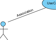 | | Definition | An association specifies a semantic relationship that can occur between typed instances. It has at least two ends represented by properties, each of which is connected to the type of the end. More than one end of the association may have the same type.
An end property of an association that is owned by an end class or that is a navigable owned end of the association indicates that the association is navigable from the opposite ends; otherwise, the association is not navigable from the opposite ends. |
| | Properties | | | Name | The name of association. | | Visibility | Determines where the association appears within different namespaces within the overall model, and its accessibility. | | Association End From | The source of association. | | Association End To | The target of association. | | Documentation | Description of association. | | Abstract | If true, the association does not provide a complete declaration and can typically not be instantiated. An abstract association is intended to be used by other associations. | | Leaf | Indicates whether it is possible to further specialize an association. If the value is true, then it is not possible to further specialize the association. | | Derived | Specifies whether the association is derived from other model elements such as other associations or constraints. |
|
|
|
| | | Collaboration | | 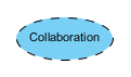 | | Definition | A collaboration is represented as a kind of classifier and defines a set of cooperating entities to be played by instances (its roles), as well as a set of connectors that define communication paths between the participating instances. The cooperating entities are the properties of the collaboration.
A collaboration specifies a view (or projection) of a set of cooperating classifiers. It describes the required links between instances that play the roles of the collaboration, as well as the features required of the classifiers that specify the participating instances. Several collaborations may describe different projections of the same set of classifiers. |
| | Properties | | | Name | The name of collaboration. | | Visibility | Determines where the collaboration appears within different namespaces within the overall model, and its accessibility. | | Documentation | Description of collaboration. | | Abstract | If true, the collaboration does not provide a complete declaration and can typically not be instantiated. An abstract collaboration is intended to be used by other collaborations. | | Leaf | Indicates whether it is possible to further specialize a collaboration. If the value is true, then it is not possible to further specialize the collaboration. | | Root | Indicates whether the collaboration has no ancestors. (true for no ancestors) | | Children | The children of collaboration |
|
|
|
| | | Constraint | | 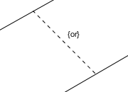 | | Definition | | A condition or restriction expressed in natural language text or in a machine readable language for the purpose of declaring some of the semantics of an element. |
| | Properties | | | Name | The name of constraint. It is optional and is commonly omitted. | | Expression | The condition that must be true when evaluated in order for the constraint to be satisfied. | | Documentation | Description of constraint. |
|
|
|
| | | Dependency | | 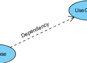 | | Definition | | A dependency is a relationship that signifies that a single or a set of model elements requires other model elements for their specification or implementation. This means that the complete semantics of the depending elements is either semantically or structurally dependent on the definition of the supplier element(s). |
| | Properties | | | Name | The name of dependency. | | Supplier | The element(s) independent of the client element(s), in the same respect and the same dependency relationship. In some directed dependency relationships (such as Refinement Abstractions), a common convention in the domain of class-based OO software is to put the more abstract element in this role. Despite this convention, users of UML may stipulate a sense of dependency suitable for their domain, which makes a more abstract element dependent on that which is more specific. | | Client | The element(s) dependent on the supplier element(s). In some cases (such as a Trace Abstraction) the assignment of direction (that is, the designation of the client element) is at the discretion of the modeler, and is a stipulation. | | Visibility | Determines where the dependency appears within different namespaces within the overall model, and its accessibility. | | Documentation | Description of dependency. |
|
|
|
| | | Extend | | 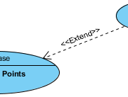 | | Definition | This relationship specifies that the behavior of a use case may be extended by the behavior of another (usually supplementary) use case. The extension takes place at one or more specific extension points defined in the extended use case. Note, however, that the extended use case is defined independently of the extending use case and is meaningful independently of the extending use case. On the other hand, the extending use case typically defines behavior that may not necessarily be meaningful by itself. Instead, the extending use case defines a set of modular behavior increments that augment an execution of the extended use case under specific conditions.
Note that the same extending use case can extend more than one use case. Furthermore, an extending use case may itself be extended. |
| | Properties | | | Name | The name of extend. | | Extension | References the use case that represents the extension and owns the extend relationship. | | Extended Case | References the use case that is being extended. | | Visibility | Determines where the extend relationship appears within different namespaces within the overall model, and its accessibility. | | Extension point | An ordered list of extension points belonging to the extended use case, specifying where the respective behavioral fragments of the extending use case are to be inserted. The first fragment in the extending use case is associated with the first extension point in the list, the second fragment with the second point, and so on. (Note that, in most practical cases, the extending use case has just a single behavior fragment, so that the list of extension points is trivial.) | | Condition | References the condition that must hold when the first extension point is reached for the extension to take place. If no constraint is associated with the extend relationship, the extension is unconditional. | | Documentation | Description of extend relationship. |
|
|
|
| | | Generalization | | 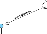 | | Definition | | A generalization is a taxonomic relationship between a more general classifier and a more specific classifier. Each instance of the specific classifier is also an indirect instance of the general classifier. Thus, the specific classifier inherits the features of the more general classifier. |
| | Properties | | | Name | The name of generalization. | | General | References the general classifier in the Generalization relationship. | | Specific | References the specializing classifier in the Generalization relationship. | | Visibility | Determines where the generalization relationship appears within different namespaces within the overall model, and its accessibility. | | Documentation | Description of generalization relationship. | | Substitutable | Indicates whether the specific classifier can be used wherever the general classifier can be used. If true, the execution traces of the specific classifier will be a superset of the execution traces of the general classifier. |
|
|
|
| | | Include | | 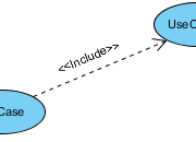 | | Definition | Include is a DirectedRelationship between two use cases, implying that the behavior of the included use case is inserted into the behavior of the including use case. It is also a kind of NamedElement so that it can have a name in the context of its owning use case. The including use case may only depend on the result (value) of the included use case. This value is obtained as a result of the execution of the included use case.
Note that the included use case is not optional, and is always required for the including use case to execute correctly. |
| | Properties | | | Name | The name of include relationship. | | Including Case | References the use case that will include the addition and owns the include relationship. | | Addition | References the use case that is to be included. | | Visibility | Determines where the include relationship appears within different namespaces within the overall model, and its accessibility. | | Documentation | Description of include relationship. |
|
|
|
| | | Note | |  | | Definition | | A note (comment) gives the ability to attach various remarks to elements. A comment carries no semantic force, but may contain information that is useful to a modeler. |
| | Properties | | | Name | The name of note. | | Documentation | Specifies a string that is the comment. |
|
|
|
| | | Realization | | 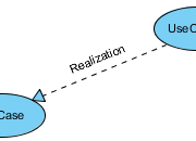 | | Definition | | Realization is a specialized abstraction relationship between two sets of model elements, one representing a specification (the supplier) and the other represents an implementation of the latter (the client). Realization can be used to model stepwise refinement, optimizations, transformations, templates, model synthesis, framework composition, etc. |
| | Properties | | | Name | The name of realization relationship. | | Supplier | The element(s) independent of the client element(s), in the same respect and the same dependency relationship. In some directed dependency relationships (such as Refinement Abstractions), a common convention in the domain of class-based OO software is to put the more abstract element in this role. Despite this convention, users of UML may stipulate a sense of dependency suitable for their domain, which makes a more abstract element dependent on that which is more specific. | | Client | The element(s) dependent on the supplier element(s). In some cases (such as a Trace Abstraction) the assignment of direction (that is, the designation of the client element) is at the discretion of the modeler, and is a stipulation. | | Visibility | Determines where the realization relationship appears within different namespaces within the overall model, and its accessibility. | | Mapping | A composition of an Expression that states the abstraction relationship between the supplier and the client. In some cases, such as Derivation, it is usually formal and unidirectional. In other cases, such as Trace, it is usually informal and bidirectional. The mapping expression is optional and may be omitted if the precise relationship between the elements is not specified. | | Documentation | Description of realization relationship. |
|
|
|
| | | System | | 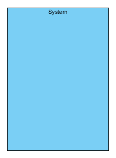 | | Definition | | If a subject (or system boundary) is displayed, the use case ellipse is visually located inside the system boundary rectangle. Note that this does not necessarily mean that the subject classifier owns the contained use cases, but merely that the use case applies to that classifier |
| | Properties | | | Name | The name of system. | | Documentation | Description of system. | | Abstract | If true, the system does not provide a complete declaration and can typically not be instantiated. An abstract system is intended to be used by other systems. | | Leaf | Indicates whether it is possible to further specialize a system. If the value is true, then it is not possible to further specialize the system. | | Root | Indicates whether the system has no ancestors. (true for no ancestors) | | Children | The use cases in the system. |
|
|
|
| | | Use Case | |  | | Definition | | A use case is the specification of a set of actions performed by a system, which yields an observable result that is, typically, of value for one or more actors or other stakeholders of the system. |
| | Properties | | | Name | The name of use case. | | ID | A unique value for identifying the use case. | | Rank | Describe the importance of the use case. The higher the ranking implies that more attention is needed. | | Documentation | Description of use case. | | Abstract | If true, the use case does not provide a complete declaration and can typically not be instantiated. An abstract use case is intended to be used by other use cases. | | Leaf | Indicates whether it is possible to further specialize an use case. If the value is true, then it is not possible to further specialize the use case. | | Root | Indicates whether the use case has no ancestors. (true for no ancestors) | | Business model | Set it to make the actor become a "business use case" | | Extension Points | References the ExtensionPoints owned by the use case. |
| | |
|
|
|
| |
| Definition of notations is quoted from Object Management Group Unified Modeling Language (OMG UML) Superstructure Version 2.2 and former versions (for notations that do not exist anymore in latest specification). |
| |
|
Use case diagram
|
Class diagram
|
Sequence diagram
|
Communication diagram
|
State machine diagram
|
Activity diagram
|
Component diagram
|
Deployment diagram
|
Package diagram
|
Object diagram
|
Composite structure diagram
|
Timing diagram
|
Interaction overview diagram
|
|
|
|
|
 |
|