Interaction overview diagram |
|
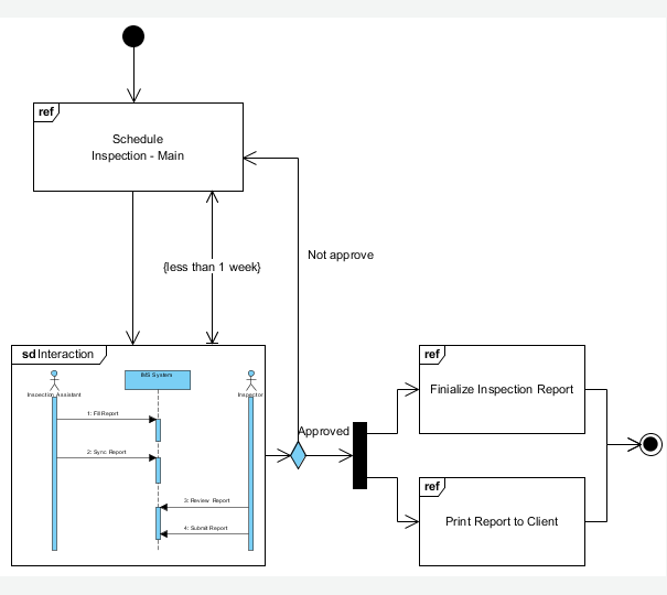
The Interaction Overview Diagram focuses on the overview of the flow of control of the interactions. It is a variant of the Activity Diagram where the nodes are the interactions or interaction occurrences. The Interaction Overview Diagram describes the interactions where messages and lifelines are hidden. You can link up the "real" diagrams and achieve high degree navigability between diagrams inside the Interaction Overview Diagram.
|
|
|
Use case diagram
|
Class diagram
|
Sequence diagram
|
Communication diagram
|
State machine diagram
|
Activity diagram
|
Component diagram
|
Deployment diagram
|
Package diagram
|
Object diagram
|
Composite structure diagram
|
Timing diagram
|
Interaction overview diagram
|
|
|
|
|
Interaction overview diagram |
|
|
|
Notation
 | | Activity Final Node |  | | Control Flow | |  | | Constraint |  | | Decision Node | |  | | Fork Node |  | | Initial Node | |  | | Interaction |  | | Interaction Use | |  | | Join Node |  | | Merge Node | |  | | Note | |
| DefinitionInteraction Overview Diagrams define Interactions through a variant of Activity Diagrams in a way that promotes overview of the control flow.
Interaction Overview Diagrams focus on the overview of the flow of control where the nodes are Interactions or InteractionUses. The Lifelines and the Messages do not appear at this overview level. |
|
| |
Activity Final Node | |  | | Definition | | An activity may have more than one activity final node. The first one reached stops all flows in the activity. |
| | Properties | | | Name | The name of activity final node. | | Visibility | Determines where the activity final node appears within different Namespaces within the overall model, and its accessibility. | | Documentation | Description of activity final node. | | Must isolate | If true, then the actions in the node execute in isolation from actions outside the node. | | Leaf | Indicates whether it is possible to further specialize an activity final node. If the value is true, then it is not possible to further specialize the activity final node. |
|
|
|
|
| |
Control Flow | | 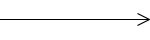 | | Definition | | A control flow is an edge that starts an activity node after the previous one is finished. |
| | Properties | | | Name | The name of control flow. | | Source | Node from which tokens are taken when they traverse the edge. | | Target | Node to which tokens are put when they traverse the edge. | | Weight | The minimum number of tokens that must traverse the edge at the same time. | | Guard | Specification evaluated at runtime to determine if the edge can be traversed. | | Documentation | Description of control flow. | | Duration Constraint | A DurationConstraint defines a Constraint that refers to a DurationInterval. |
|
|
|
|
| |
Constraint | | 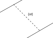 | | Definition | | A condition or restriction expressed in natural language text or in a machine readable language for the purpose of declaring some of the semantics of an element. |
| | Properties | | | Name | The name of constraint. It is optional and is commonly omitted. | | Expression | The condition that must be true when evaluated in order for the constraint to be satisfied. | | Documentation | Description of constraint. |
|
|
|
|
| |
Decision Node | |  | | Definition | | A decision node accepts tokens on an incoming edge and presents them to multiple outgoing edges. Which of the edges is actually traversed depends on the evaluation of the guards on the outgoing edges. |
| | Properties | | | Name | The name of decision node. | | Visibility | Determines where the decision node appears within different Namespaces within the overall model, and its accessibility. | | Documentation | Description of decision node. | | Must isolate | If true, then the actions in the node execute in isolation from actions outside the node. | | Leaf | Indicates whether it is possible to further specialize a decision node. If the value is true, then it is not possible to further specialize the decision node. |
|
|
|
|
| |
Fork Node | |  | | Definition | | A fork node is a control node that splits a flow into multiple concurrent flows. A fork node has one incoming edge and multiple outgoing edges. |
| | Properties | | | Name | The name of fork node. | | Visibility | Determines where the fork appears within different Namespaces within the overall model, and its accessibility. | | Documentation | Description of fork. | | Must isolate | If true, then the actions in the node execute in isolation from actions outside the node. | | Leaf | Indicates whether it is possible to further specialize a fork node. If the value is true, then it is not possible to further specialize the fork node. |
|
|
|
|
| |
Initial Node | |  | | Definition | | An initial node is a control node at which flow starts when the activity is invoked. An activity may have more than one initial node. |
| | Properties | | | Name | The name of initial node. | | Visibility | Determines where the initial node appears within different Namespaces within the overall model, and its accessibility. | | Documentation | Description of initial node. | | Must isolate | If true, then the actions in the node execute in isolation from actions outside the node. | | Leaf | Indicates whether it is possible to further specialize an initial node. If the value is true, then it is not possible to further specialize the initial node. |
|
|
|
|
| |
Interaction | | 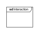 | | Definition | | An interaction is a unit of behavior that focuses on the observable exchange of information between ConnectableElements. |
| | Properties | | | Name | The name of interaction. | | Documentation | Description of interaction. | | Duration Constraint | A DurationConstraint defines a Constraint that refers to a DurationInterval. |
|
|
|
|
| |
Interaction Use | |  | | Definition | An InteractionUse refers to an Interaction. The InteractionUse is a shorthand for copying the contents of the referred Interaction where the InteractionUse is. To be accurate the copying must take into account substituting parameters with arguments and connect the formal gates with the actual ones.
It is common to want to share portions of an interaction between several other interactions. An InteractionUse allows multiple interactions to reference an interaction that represents a common portion of their specification. |
| | Properties | | | Name | The name of interaction use. | | Return value | The value return by the interaction. | | Refers to | Refers to the Interaction that defines its meaning. | | Documentation | Description of interaction use. | | Attribute | The attribute-name refers to an attribute of one of the lifelines in the Interaction. | | Arguments | The actual arguments of the Interaction. | | Duration Constraint | A DurationConstraint defines a Constraint that refers to a DurationInterval. | | Covered LifeLines | The InteractionUse must cover all Lifelines of the enclosing Interaction that appear within the referred Interaction. |
|
|
|
|
| |
Join Node | |  | | Definition | | A join node is a control node that synchronizes multiple flows. A join node has multiple incoming edges and one outgoing edge. |
| | Properties | | | Name | The name of join node. | | Visibility | Determines where the join node appears within different Namespaces within the overall model, and its accessibility. | | Documentation | Description of join node. | | Must isolate | If true, then the actions in the node execute in isolation from actions outside the node. | | Leaf | Indicates whether it is possible to further specialize a join node. If the value is true, then it is not possible to further specialize the join node. |
|
|
|
|
| |
Merge Node | |  | | Definition | | A merge node is a control node that brings together multiple alternate flows. It is not used to synchronize concurrent flows but to accept one among several alternate flows. A merge node has multiple incoming edges and a single outgoing edge. |
| | Properties | | | Name | The name of merge node. | | Visibility | Determines where the merge node appears within different Namespaces within the overall model, and its accessibility. | | Documentation | Description of merge node. | | Must isolate | If true, then the actions in the node execute in isolation from actions outside the node. | | Leaf | Indicates whether it is possible to further specialize a merge node. If the value is true, then it is not possible to further specialize the merge node. |
|
|
|
|
| |
Note | |  | | Definition | | A note (comment) gives the ability to attach various remarks to elements. A comment carries no semantic force, but may contain information that is useful to a modeler. |
| | Properties | | | Name | The name of note. | | Documentation | Specifies a string that is the comment. |
|
|
|
|
| |
| Definition of notations is quoted from Object Management Group Unified Modeling Language (OMG UML) Superstructure Version 2.2 and former versions (for notations that do not exist anymore in latest specification). |
| |
|
Use case diagram
|
Class diagram
|
Sequence diagram
|
Communication diagram
|
State machine diagram
|
Activity diagram
|
Component diagram
|
Deployment diagram
|
Package diagram
|
Object diagram
|
Composite structure diagram
|
Timing diagram
|
Interaction overview diagram
|