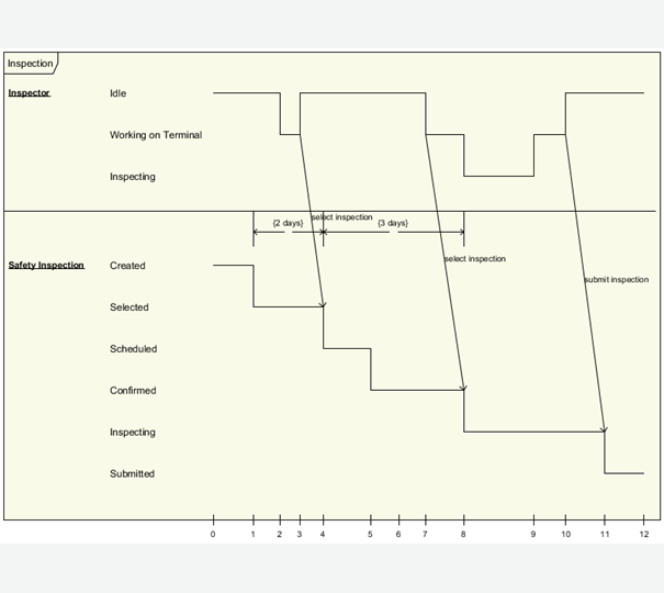
Timing Diagram shows the behavior of the object(s) in a given period of time. Timing diagram is a special form of a sequence diagram. The differences between timing diagram and sequence diagram are the axes are reversed so that the time are increase from left to right and the lifelines are shown in separate compartments arranged vertically. Visual Paradigm supports both discrete timing and the general value lifeline style.
Timing Diagrams are used to show interactions when a primary purpose of the diagram is to reason about time. Timing diagrams focus on conditions changing within and among Lifelines along a linear time axis. Timing diagrams describe behavior of both individual classifiers and interactions of classifiers, focusing attention on time of occurrence of events causing changes in the modeled conditions of the Lifelines.
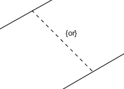
Constraint
Definition
A condition or restriction expressed in natural language text or in a machine readable language for the purpose of declaring some of the semantics of an element.
Properties
Name
The name of constraint. It is optional and is commonly omitted.
Expression
The condition that must be true when evaluated in order for the constraint to be satisfied.
Documentation
Description of constraint.
Note
Definition
A note (comment) gives the ability to attach various remarks to elements. A comment carries no semantic force, but may contain information that is useful to a modeler.
Properties
Name
The name of note.
Documentation
Specifies a string that is the comment.
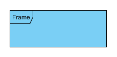
Timing Frame
Definition
An interaction is a unit of behavior that focuses on the observable exchange of information between ConnectableElements.