A state machine Diagram (or start diagram, also called state chart of state transition diagram) is a behavior which specifies the sequence of states an entity (or object) visits during its lifetime in response to events, together with its responses to those events.
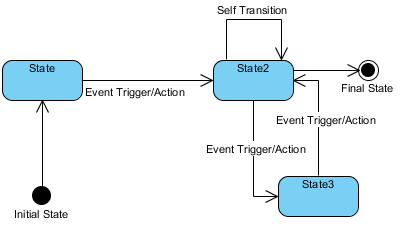
State diagram at a glance
Key concepts
State
A state is a condition during the life of an object during which it satisfies some condition, performs some activity, or waits for some external event
Event
An event is the specification of a significant occurrence. For a state machine, an event is the occurrence of a stimulus that can trigger a state transition.
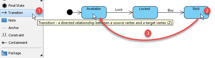
Transition
A transition is a relationship between two states indicating that an object in the first state will, when a specified set of events and conditions are satisfied, perform certain actions and enter the second state.
Action
An action is an executable, atomic (with reference to the state machine) computation. Actions may include operations, the creation or destruction of other objects, or the sending of signals to other objects (events).
Creating a State Machine Diagram
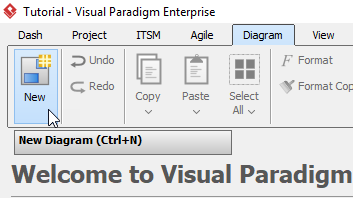
- Select Diagram > New from the tool bar.
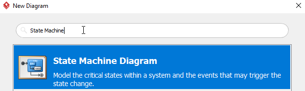
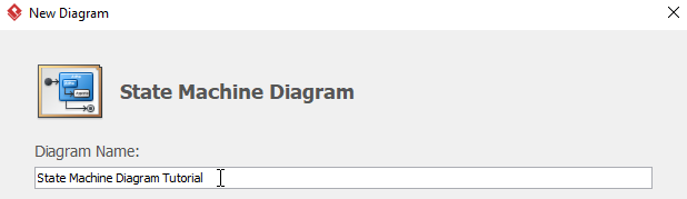
- In the New Diagram window, select State Machine Diagram, then click Next. you can use the search bar above to filter results.
- Name the diagram, then click OK. In this tutorial, we will name the diagram State Machine Diagram Tutorial.
- You will now see an empty diagram with an initial pseudo state.
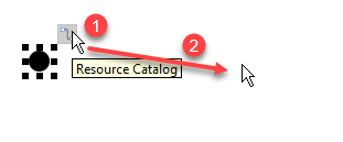
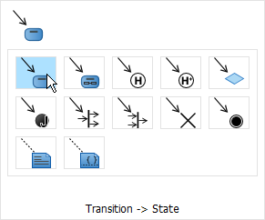
- To Create a new state, click the initial state, then drag the resource button to the desire position and release. When release the button, choose Transition -> State from the popup window. Once the state is created, you may change the name of the state.
- Repeat step 5 for more states.
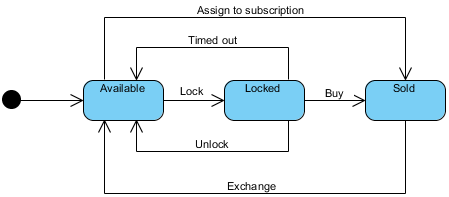
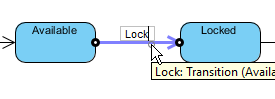
- No you may see the transitions are not named. You can name a transition by double clicking the transition. This example will name the transition between Available and Locked to Lock.
- Once all the states are created, you may want to set up more transitions. You can do this by selecting Transition, click and hold on the starting state (Sold in this example), then drag to the destination state (Available in this example) and release. Do not forget to name the transition.
- You are expected to see a diagram like this when you finish your diagram: