A business goal is a target that an organization aims to achieve by performing correctly the related business process.
“A business process consists of a set of activities that are performed in coordination in an organizational and technical environment. These activities jointly realize a business goal”
The primary goal of the BPMN effort was to provide a notation that is readily understandable by all business users, from the business analysts that create the initial drafts of the processes, to the technical developers responsible for implementing the technology that will perform those processes, and finally, to the business people who will manage and monitor those processes.
BPMN can also be supported by an internal model that will enable the generation of executable BPEL4WS. Thus, BPMN creates a standardized bridge for the gap between the business process design and process implementation. Thus, BPMN can be applied in three different levels:
A BPD is made up of a set of graphical elements. These elements enable the easy development of simple diagrams that will look familiar to most business analysts (e.g., a flowchart diagram). The elements were chosen to be distinguishable from each other and to utilize shapes that are familiar to most modelers.
For example, activities are rectangles and decisions are diamonds. It should be emphasized that one of the drivers for the development of BPMN is to create a simple mechanism for creating business process models, while at the same time being able to handle the complexity inherent to business processes.
The approach taken to handle these two conflicting requirements was:
The four basic categories of elements are:
A BPD has a small set of (three) core elements, which are the Flow Objects so that modelers do not have to learn and recognize a large number of different shapes. The three Flow Objects are:
Event
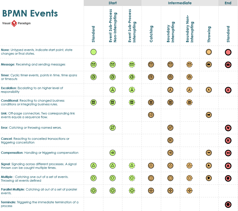
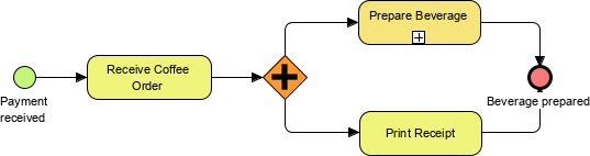
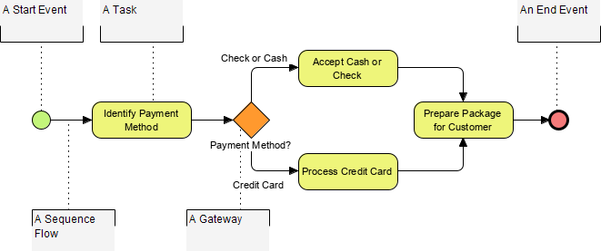
An Event is represented by a circle and is something that “happens” during the course of a business process. These Events affect the flow of the process and usually have a cause (trigger) or an impact (result). Events are circles with open centers to allow internal markers to differentiate different triggers or results. There are three types of Events, based on when they affect the flow: Start, Intermediate, and End (see the figures to the right, respectively).
Activity
An Activity is represented by a rounded-corner rectangle (see the figure to the right) and is a generic term for work that the company performs. An Activity can be atomic or nonatomic (compound). The types of Activities are Task and Sub-Process. The Sub-Process is distinguished by a small plus sign in the bottom center of the shape.
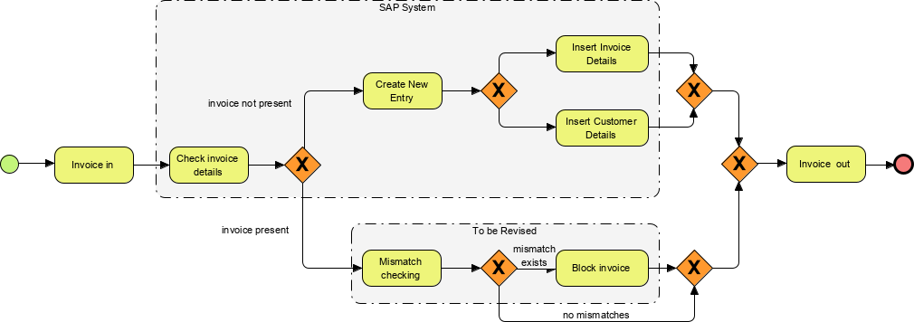
Gateway
A Gateway is represented by the familiar diamond shape
and is used to control the divergence and convergence of Sequence Flow. Thus, it will determine traditional decisions, as well as the forking, merging, and joining of paths. Internal Markers will indicate the type of behavior control.
| Exclusive Gateway
Follow only one path |
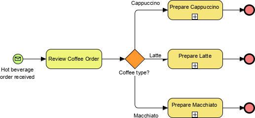 |
| Inclusive
Follow one or more paths |
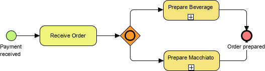 |
| Parallel
Follow all paths |
 |
![]()

The flow objects are connected together in a diagram to create the basic skeletal structure of a business process. There are three Connecting Objects that provide this function. These connectors are:
Sequence Flow
A Sequence Flow is represented by a solid line with a solid arrowhead (see the figure to the right) and is used to show the order (the sequence) that activities will be performed in a Process. Note that the term “control flow” is generally not used in BPMN.
Message Flow
A message Flow symbolizes information flow across organizational boundaries. Message flow can be attached to pools, activities, or message events. The Message Flow can be decorated with an envelope depicting the content of the message.
Association
Annotations allow additional information relevant in documenting the process to be shown on the diagram.
![]()
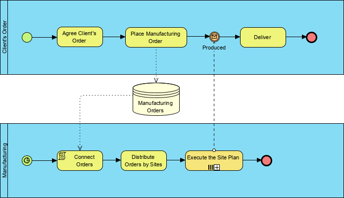
Many process modeling methodologies utilize the concept of swimlanes as a mechanism to organize activities into separate visual categories in order to illustrate different functional capabilities or responsibilities. BPMN supports swimlanes with two main constructs.
The two types of BPD swimlane objects are:
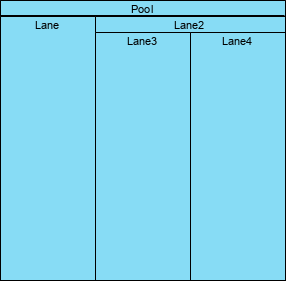
Pool – A Pool represents a Participant in a Process. It also acts as a graphical container for partitioning a set of activities from other Pools (see the figure to the right), usually in the context of B2B situations.
Lane – A Lane is a sub-partition within a Pool and will extend the entire length of the Pool, either vertically or horizontally (see the figure to the right). Lanes are used to organize and categorize activities.
BPMN was designed to allow modelers and modeling tools some flexibility in extending the basic notation and in providing the ability to add a context appropriate to a specific modeling situation, such as for a vertical market (e.g., insurance or banking). Any number of Artifacts can be added to a diagram as appropriate for the context of the business processes being modeled. The current version of the BPMN specification pre-defines only three types of BPD Artifacts, which are:
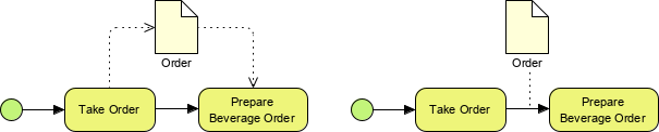
Data Object
Data Objects are a mechanism to show how data is required or produced by activities. They are connected to activities through Associations.
Data Store
A datastore is somewhere that the process can read or write data, that persists beyond the scope of the process.
Group
A Group is represented by a rounded-corner rectangle drawn with a dashed line (see the figure to the right). The grouping can be used for documentation or analysis purposes but does not affect the Sequence Flow.
Annotation
Annotations are a mechanism for a modeler to provide additional text information for the reader of a BPMN Diagram (see the figure to the right). In this example, the annotations are used to explain the BPMN elements:
As I mentioned above, within the basic categories of elements, additional variation and information can be added to support the requirements for complexity without dramatically changing the basic look-and-feel of the diagram.
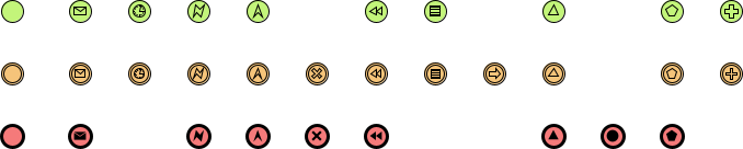
The event table below shows the complete combination of how events can be represented by using the basic element with an additional variation. BPMN events now can support for complexity without changing the basic look & feel of the notation: