A Use case has been viewed as a mechanism to capture system requirements in terms of the uses of the system which specifies the expected behavior (what), and not the exact method of making it happens (how) of a system and thus, it is a black-box view of the system; it is therefore well suited to serve as a system context diagram.
Use cases once specified can be denoted both textual and visual representation (i.e. use case diagram). A key concept of use case modeling is that it helps us design a system from the end user’s perspective. It is an effective technique for communicating system behavior in the user’s terms by specifying all externally visible system behaviors.
Use Case Diagram at a Glance
A standard form of use case diagram is defined in the Unified Modeling Language as shown in the Use Case Diagram example below:
Major Use Case Diagram Symbols
Association Link
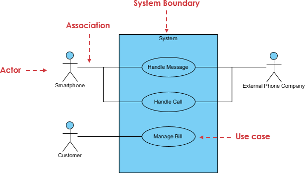
A Use Case diagram illustrates a set of use cases for a system, i.e. the actors and the relationships between the actors and use cases.
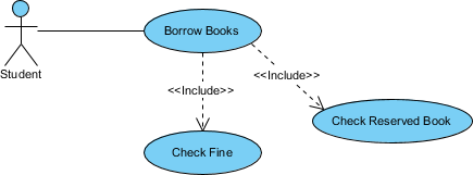
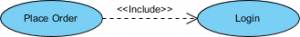
Include Relationship
The include relationship adds additional functionality not specified in the base use case. The <<Include>> relationship is used to include common behavior from an included use case into a base use case to support the reuse of common behavior.
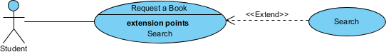
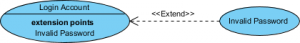
Extend Relationship
The extend relationships are important because they show optional functionality or system behavior. The <<extend>> relationship is used to include optional behavior from an extending use case in an extended use case. Take a look at the use case diagram example below. It shows an extend connector and an extension point “Search”.
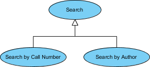
Generalization Relationship
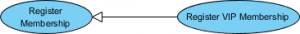
A generalization relationship means that a child use case inherits the behavior and meaning of the parent use case. The child may add or override the behavior of the parent. The figure below provides a use case example by showing two generalization connectors that connect between the three use cases.
How to Identify Actor
Often, people find it easiest to start the requirements elicitation process by identifying the actors. The following questions can help you identify the actors of your system (Schneider and Winters – 1998):
- Who uses the system?
- Who installs the system?
- Who starts up the system?
- Who maintains the system?
- Who shuts down the system?
- What other systems use this system?
- Who gets information from this system?
- Who provides information to the system?
- Does anything happen automatically at a present time?
Levels of Details
Use case granularity refers to how information is organized within use case specifications, and to some extent, the level of detail at which they are written. Achieving the right level of use case granularity eases communication between stakeholders and developers and improves project planning.
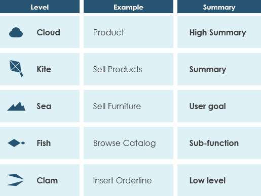
Alastair Cockburn in Writing Effective Use Cases gives us an easy way to visualize different levels of goal level by thinking in terms of the sea:
Top Level Use Cases
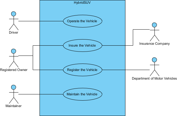
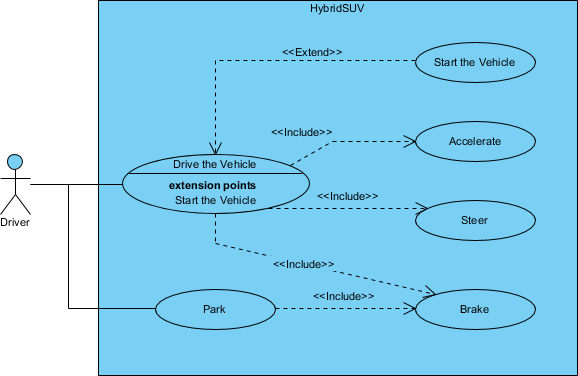
The use case diagram for “Drive Vehicle” in Figure 5 depicts the drive vehicle usage of the vehicle system. The subject (Hybrid SUV) and the actors (Driver, Registered Owner, Maintainer, Insurance Company, DMV) interact to realize the use case.
Operational Use Cases
Goal-level Use Cases associated with “Operate the Vehicle” are depicted in the following diagram. These use cases help flesh out the specific kind of goals associated with driving and parking the vehicle. Maintenance, registration, and insurance of the vehicle would be covered under a separate set of goal-oriented use cases.
Use Case Diagram Notation Summary
| Notation Description |
Visual Representation |
Actor
- Someone interacts with the use case (system function).
- Named by a noun.
- Actor plays a role in the business
- Similar to the concept of a user, but a user can play different roles
- For example:
- A prof. can be an instructor and also a researcher
- plays 2 roles with two systems
- Actor triggers use case(s).
- Actor has a responsibility toward the system (inputs), and Actor has expectations from the system (outputs).
|
 |
Use Case
- System function (process – automated or manual)
- Named by verb + Noun (or Noun Phrase).
- i.e. Do something
- Each Actor must be linked to a use case, while some use cases may not be linked to actors.
|
 |
Association Link
- The participation of an actor in a use case is shown by connecting an actor to a use case by a solid link.
- Actors may be connected to use cases by associations, indicating that the actor and the use case communicate with one another using messages.
|
 |
Boundary of system
- The system boundary is potentially the entire system as defined in the requirements document.
- For large and complex systems, each module may be the system boundary.
- For example, for an ERP system for an organization, each of the modules such as personnel, payroll, accounting, etc.
- can form a system boundary for use cases specific to each of these business functions.
- The entire system can span all of these modules depicting the overall system boundary
|
 |
Extends
- Indicates that an “Invalid Password” use case may include (subject to specified in the extension) the behavior specified by base use case “Login Account”.
- Depict with a directed arrow having a dotted line. The tip of arrowhead points to the base use case and the child use case is connected at the base of the arrow.
- The stereotype “<<extends>>” identifies as an extend relationship
|
 |
Include
- When a use case is depicted as using the functionality of another use case, the relationship between the use cases is named as include or uses relationship.
- A use case includes the functionality described in another use case as a part of its business process flow.
- A uses relationship from base use case to child use case indicates that an instance of the base use case will include the behavior as specified in the child use case.
- An include relationship is depicted with a directed arrow having a dotted line. The tip of arrowhead points to the child use case and the parent use case connected at the base of the arrow.
- The stereotype “<<include>>” identifies the relationship as an include relationship.
|
 |
Generalization
- A generalization relationship is a parent-child relationship between use cases.
- The child use case is an enhancement of the parent use case.
- Generalization is shown as a directed arrow with a triangle arrowhead.
- The child use case is connected at the base of the arrow. The tip of the arrow is connected to the parent use case.
|
 |
Use Case Diagram Examples
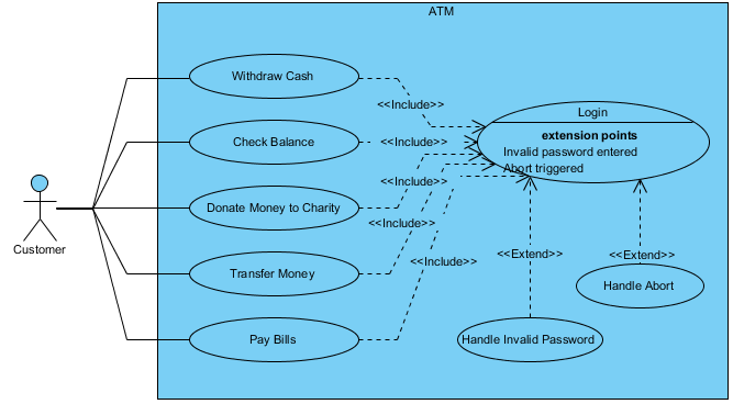
ATM example
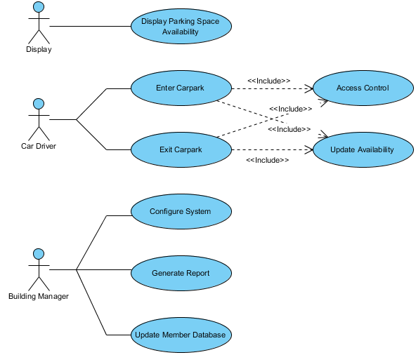
Carpark system