The block definition diagram Derived from the UML Class Diagram is the most widely-used diagram for modeling the static structure of a system. It is often be used to declare Blocks and their compositional, logical, and generalization / Inheritance relationships.
Inherited from the UML, Classes, and Objects become Blocks and their instances, while parts can be tied together by Connectors; a physical connection between instances of Parts is a Link; Connectors can be typed by associations that can be defined by Association Blocks. You can display various kinds of model elements and relationships on a BDD to express information about a system’s structure.
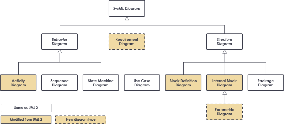
The main structural representations are the Block Definition Diagram (BDD), which is a modification of the UML Class Diagram, and the Internal Block Diagram (IBD), which is modified from the UML Composite Structure Diagram.
You can display various kinds of model elements and relationships on a BDD to express information about a system’s structure. You can also adopt design techniques for creating extensible system structures, a practice that reduces the time and cost to change your design as your stakeholders’ needs evolve.
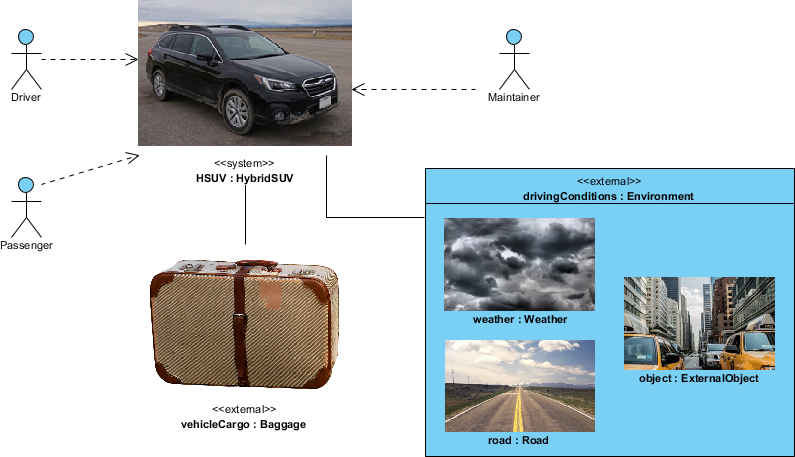
We can make use of a user-defined usage (by using some UML stereotypes) of an internal block diagram (often called system context diagram) to depict some of the top-level entities in the overall enterprise and their relationships. The entities are conceptual during the initial phase of development but will be refined as part of the development process for using the use case diagram and block definition diagram. The relationships in this diagram are also reflected in the Automotive Domain Model Block Definition Diagram will be shown in the later section.
This user-defined IBD usage enables the modeler or methodologist to specify a unique usage of a SysML diagram type using the extension mechanism by defining the following:
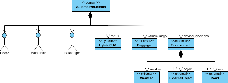
The high-level block definition diagram shown below defines the concepts previously shown in the context diagram example above.
This lower level block definition diagram defines components of the HybridSUV block.
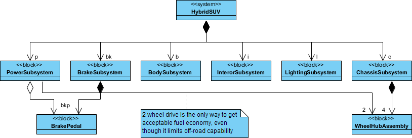
Note that the BrakePedal and WheelHubAssembly are used by, but not contained in, the PowerSubsystem block.