Collaboration diagrams (known as Communication Diagram in UML 2.x) are used to show how objects interact to perform the behavior of a particular use case, or a part of a use case. Along with sequence diagrams, collaboration are used by designers to define and clarify the roles of the objects that perform a particular flow of events of a use case. They are the primary source of information used to determining class responsibilities and interfaces.
| Learn UML Faster, Better and Easier |
| Are you looking for a Free UML tool for learning UML faster, easier and quicker? Visual Paradigm Community Edition is a UML software that supports all UML diagram types. It is an international award-winning UML modeler, and yet it is easy-to-use, intuitive & completely free. |
| [Free Download] |
What is a Collaboration?
- A Collaboration is a collection of named objects and actors with links connecting them. They collaborate in performing some task.
- A Collaboration defines a set of participants and relationships that are meaningful for a given set of purposes
- A Collaboration between objects working together provides emergent desirable functionalities in Object-Oriented systems
- Each object (responsibility) partially supports emergent functionalities
- Objects are able to produce (usable) high-level functionalities by working together
- Objects collaborate by communicating (passing messages) with one another in order to work together
Why Collaboration Diagram?
Unlike a sequence diagram, a collaboration diagram shows the relationships among the objects. Sequence diagrams and collaboration diagrams express similar information, but show it in different ways.
Because of the format of the collaboration diagram, they tend to better suited for analysis activities (see Activity: Use-Case Analysis). Specifically, they tend to be better suited to depicting simpler interactions of smaller numbers of objects. However, if the number of objects and messages grows, the diagram becomes increasingly hard to read. In addition, it is difficult to show additional descriptive information such as timing, decision points, or other unstructured information that can be easily added to the notes in a sequence diagram. So, here are some use cases that we want to create a collaboration diagram for:
- Model collaborations between objects or roles that deliver the functionalities of use cases and operations
- Model mechanisms within the architectural design of the system
- Capture interactions that show the messages passing between objects and roles within the collaboration
- Model alternative scenarios within use cases or operations that involve the collaboration of different objects and interactions
- Support the identification of objects (hence classes) that participate in use cases
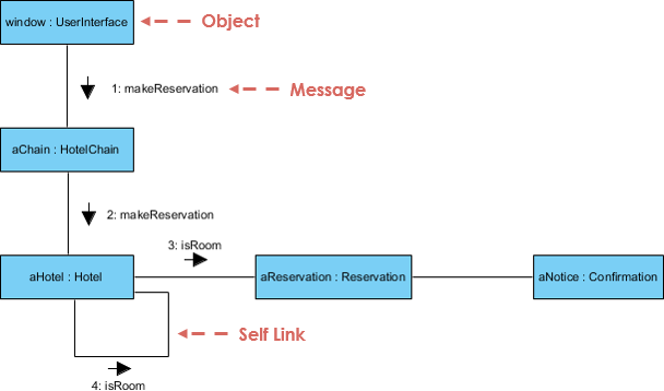
- Each message in a collaboration diagram has a sequence number.
- The top-level message is numbered 1. Messages sent during the same call have the same decimal prefix but suffixes of 1, 2, etc. according to when they occur.
Notations of Collaboration Diagram
Objects
An object is represented by an object symbol showing the name of the object and its class underlined, separated by a colon:
Object_name : class_name
You can use objects in collaboration diagrams in the following ways:
- Each object in the collaboration is named and has its class specified
- Not all classes need to appear
- There may be more than one object of a class
- An object’s class can be unspecified. Normally you create a collaboration diagram with objects first and specify their classes later.
- The objects can be unnamed, but you should name them if you want to discriminate different objects of the same class.
Actors
Normally an actor instance occurs in the collaboration diagram, as the invoker of the interaction. If you have several actor instances in the same diagram, try keeping them in the periphery of the diagram.
- Each Actor is named and has a role
- One actor will be the initiator of the use case
Links
Links connect objects and actors and are instances of associations and each link corresponds to an association in the class diagram
Links are defined as follows:
- A link is a relationship among objects across which messages can be sent. In collaboration diagrams, a link is shown as a solid line between two objects.
- An object interacts with, or navigates to, other objects through its links to these objects.
- A link can be an instance of an association, or it can be anonymous, meaning that its association is unspecified.
- Message flows are attached to links, see Messages.
Messages
A message is a communication between objects that conveys information with the expectation that activity will ensue. In collaboration diagrams, a message is shown as a labeled arrow placed near a link.
- The message is directed from sender to receiver
- The receiver must understand the message
- The association must be navigable in that direction
Steps for Creating Collaboration Diagrams
- Identify behavior whose realization and implementation is specified
- Identify the structural elements (class roles, objects, subsystems) necessary to carry out the functionality of the collaboration
- Decide on the context of interaction: system, subsystem, use case and operation
- Model structural relationships between those elements to produce a diagram showing the context of the interaction
- Consider the alternative scenarios that may be required
- Draw instance level collaboration diagrams, if required.
- Optionally draw a specification level collaboration diagram to summarize the alternative scenarios in the instance level sequence diagrams
Collaboration Diagram Example
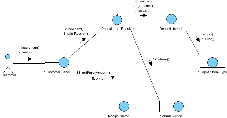
Collaboration Diagram in Robustness Diagram Format
You can have objects and actor instances in collaboration diagrams, together with links and messages describing how they are related and how they interact. The Receive Deposit Item in the Recycling-Machine System diagram shown below describes what takes place in the participating objects, in terms of how the objects communicate by sending messages to one another. You can make a collaboration diagram for each variant of a use case’s flow of events.
| Try to Draw UML Collaboration Diagram Now |
| You’ve learned what a Collaboration Diagram is and how to draw a Collaboration Diagram. It’s time to draw a Collaboration Diagram of your own. Get Visual Paradigm Community Edition, a free UML software, and create your own Collaboration Diagram with the free Collaboration Diagram tool. It’s easy-to-use and intuitive. |
| [Free Download] |