Track the Occurrence of Glossary Term in Project
A word can mean different things under different domains. In Visual Paradigm, you can standardize the meaning of the wordings by defining it as a glossary term. However, since a term can be used in various model elements, it's hard to find out a glossary term being used in which model elements. With Visual Paradigm, you are able to look over all model elements which share the same term using analysis diagram. In this tutorial, you will learn how to identify the model elements which using particular glossary term through the use of analysis diagram.
- Download Apply university.vpp from this tutorial in advance.
- Open the project with Visual Paradigm. You can open a project by selecting Project > Open from the application toolbar.
- Open the only use case diagram and take a look.
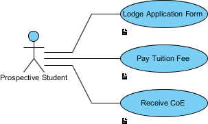
- Descriptions have been entered for the three use cases. Let's check. Open the description pane by clicking Show Description on the right-hand side of the status bar.

- Click on the use case Lodge Application Form. You can read the description in the description pane. Read also the description of the other use cases on the diagram.

- Select the use case Lodge Application Form.
- Extract a keyword as a glossary term. In this tutorial, highlight tuition fee with the mouse and right-click on it to select Add "tuition fee" to Glossary from the pop-up menu.

- You should see a message appear on the status bar, telling you that the term tuition fee has been added to the glossary grid. Click on the link of the glossary grid to go there. If you have missed that, do not worry. You can open the glossary grid by selecting Modeling > Glossary > Glossary Grid from the application toolbar.

- The glossary grid will appear, with the term tuition fee shown in the grid.

- Assume you want to modify the meaning of the term. You may wonder how you can know which models will be affected. In Visual Paradigm, you can find this out by creating an analysis diagram on the glossary term. Right-click on tuition fee and select Analysis... from the pop-up menu.

- In the pop-up Analysis window, Create new diagram will be selected and a new diagram name will be filled by default. Click OK to proceed.

- An Analysis Diagram is created as shown below:

The oval node at the center of the analysis diagram indicates the term you have chosen for analyzing. The connectors branching out are the relationships with the analyzing term, and the nodes at the opposite end of the connectors are the related elements. You can see a tag (e.g., <<Model>>), which indicates the type of that related element, and the name of the related element is placed under the tag inside the node. By reading the analysis diagram, you can identify the relationship of a model element and discover all model elements which share the same term. - Select a model to open its view in the original diagram. For example, move the mouse pointer over Receive CoE and click its resource icon Open View.

As a result, it jumps to the original diagram.