How to Draw UML Diagrams in NetBeans?
Tired of switching between your favourite IDE to modelling environment to get work done? Also feeling troublesome to sync between code and visual models in two separated development environments? Visual Paradigm seamlessly integrated with NetBeans, providing full support of round-trip code and database engineering. Developers can now perform full lifecycle development activities with NetBeans, such as analysis, design modelling, code engineering, agile teamwork development and much more!
Visual Paradigm is an award-winning agile development platform that encompasses widely-used agile toolsets such as user story, use case, UML visual model, coding engineering, teamwork, and project management capabilities. This one-stop solution enables developers to carry out the entire agile development process within one place.
Preparation
To follow and complete this tutorial, you must have Visual Paradigm installed. It can be downloaded from the Visual Paradigm download page. Of course, you also need the NetBeans IDE. We suppose you have already installed it, but if you haven't, please download and install it from the NetBeans official site.
Note: We only support NetBeans 6.7 or upper versions. If you are using an earlier version, please consider upgrading your NetBeans.
Visual Paradigm targets software teams who want to develop software with professional design, reporting, code, and database engineering support. It supports all sorts of UML modeling features, Business Process Modeling with OMG's Business Process Modeling Notation (BPMN), ERD (for database design), code generation, reverse engineering, database generation/reversal, Hibernate, report composer, and report generation.
Integrate Visual Paradigm with NetBeans
Here we go. We need to install the integration from Visual Paradigm. So, turn off your NetBeans and start Visual Paradigm. Perform the steps below.
- In Visual Paradigm, select Window > Integration > IDE Integration... from the application toolbar.

- In the Visual Paradigm IDE Integration window, check NetBeans Integration. Click Next.

-
Specify the path of your NetBeans installation and click Next.

This begins file copying. If you see the error messages "java.io.IOException: Cannot make dirs for file...", please restart Visual Paradigm with the Run as Administrator option. When finished copying files, close Visual Paradigm and move on to the next section to see how to create a Java application in NetBeans along with the UML model.
Creating a UML Model for Your Java Project
In this section, we are going to create a UML model from a Java project in NetBeans. To avoid interfering with your production work, we will create a new Java project for this tutorial.
- Start the NetBeans IDE.
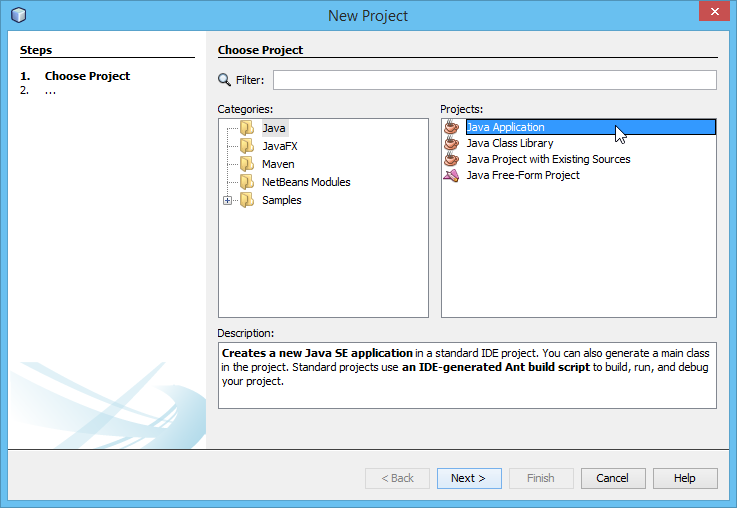
- Click the New Project button on the toolbar to open the New Project window.

- In the New Project window, select the Java category and choose Java Class Library as the project type. Click Next.
- Enter Online Shop in the Project Name field. Leave other settings as default and click Finish to create the project.

- Now, you have an empty Java project. Let's create a UML model from it. To create a UML model, right-click on the project root node in the Projects pane and select Open Visual Paradigm from the popup menu.

- When you are prompted to enter the path of the project file, keep Create in default path selected and click OK. This will create the .vpp project file in the Java project folder.

UML Modeling in NetBeans
Let's draw a simple class diagram. We will generate Java code from it in the next section.
- Open the Diagram Navigator of Visual Paradigm.

- Right-click on the Class Diagram node and select New Class Diagram from the popup menu. This creates an empty class diagram.

- The diagram will automatically grab focus on its package header (top left of diagram). This allows you to specify the parent package for your diagram. If the package you specified does not exist in your project, it will be created for you automatically. Once you have specified the package, the class diagram along with the classes to be created in the diagram will automatically be put in the package. Enter onlineshop as the package name and press Enter.

- Now, the focus will shift to the diagram name field. Enter Online Shop as the name of the diagram and then press Enter.

- Next, we are going to create a class. Select Class from the diagram toolbar and drag it onto the diagram to create a class.

- Enter Product as the name and press Enter to confirm.

- A product has three attributes: name, partNo, and price. Let's add them. Right-click on the Product class and select Add > Attribute with Getter and Setter from the popup menu.

- Enter name : String to create the name attribute in String type. Then, press Enter to confirm. Right after your confirmation, the getter and setter operations for the name attribute will automatically be inserted into the class. Similarly, create two more attributes: partNo : String and price : float.

- Press Esc to cancel the next attribute.
Generate Java Code from a Class Diagram
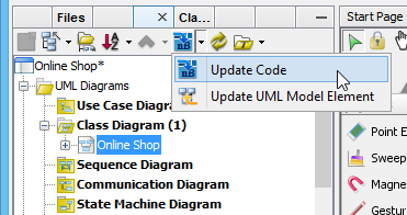
Let's generate Java source code from the UML class. There are several ways to achieve this. Here, let's try the one that generates code for the entire UML model. Click on the Update Code button at the top of the Diagram Navigator.
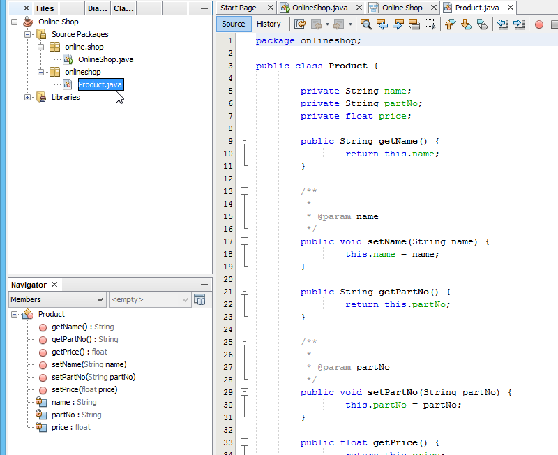
In the Projects pane, expand the project node and check Source Packages. The package onlineshop and Product class are there. Open Product.java; you can see the Product class filled with attributes and its getter and setter.
Generate and Update UML Classes from Java Code
You've learned how to create UML diagrams in NetBeans. If you want to know how to produce a UML class model from your Java source code, which is essential to keep the design conformed to your source code, you need to perform the steps below.
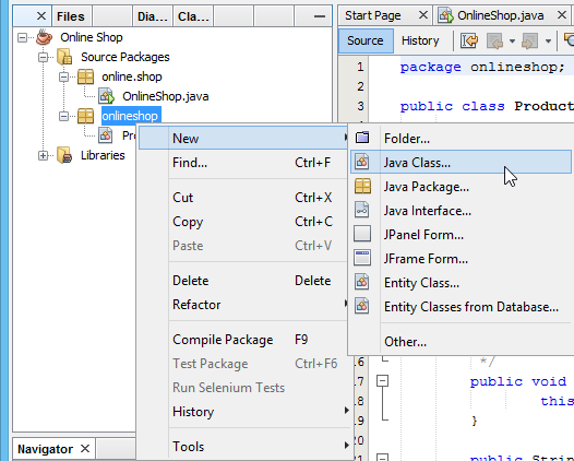
- Let's create a class in NetBeans. Right-click on the package onlineshop and select New > Java Class... from the popup menu.
- In the New Java Class window, enter Vendor as the class name and click Finish.

- Add two attributes to the Vendor class: a name in String type and a collection of Product.

- Next, we try to update the Product class which was just generated in the previous step. Let's try to add a constructor to it. Right-click on the source file of the Product class and select Insert Code.

- Select Constructor... from the popup pane.

- Select all three attributes and click Generate to generate the constructor.

- Now, go to the Diagram Navigator. Click on the Update UML Model Element button to have your changes reflected in the UML model.

- Open the class diagram. The constructor method is presented in the Product class.

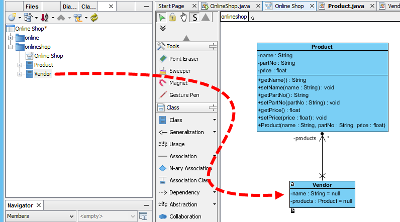
- Switch to the Model Explorer pane. You can find the Vendor class inside the onlineshop package. Drag out the Vendor class and drop it onto the class diagram. The Vendor class will be visualized with an association with the Product class.
Something More - Generate a UML Sequence Diagram from Java Code
The class diagram helps you understand the static data structure of your system. However, what about its dynamic behavior? A Sequence diagram is one of the popular diagrams in UML used to model the dynamic behavior of a system. You can reverse-engineer Java source code into a sequence diagram inside the NetBeans integration environment. Let's walk through the steps below to create a sequence diagram from source code. Before you start, please note that the classes drawn in the previous sections will be overwritten by the steps to be performed.
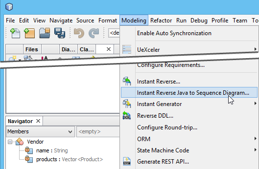
- Select Modeling > Instant Reverse Java to Sequence Diagram... from the menu.
- Click the Add Source Folder button in the Instant Reverse Java to Sequence Diagram window.

- Specify the source folder of the Java project in the Select Directories window. Click OK and then click Next.

- Now, expand the tree in the Select Operation step and choose the operation you would like to reverse to a sequence diagram. Click Next to proceed.

- Select Create New Sequence Diagram in the Choose Diagram step and leave the diagram name as default. Click Finish.

Now the sequence diagram of your selected operation is being generated.