How to Draw SysML Requirement Diagram?
A SysML requirement diagram enables you to visualize any kind of requirements of your system, both functinal and non-functional. You can also visualize the inter-relationships between requirements. By using SysML requirement diagram with UeXceler, you have a complete set of system requirements that involve the business goal, the user stories that describe user problems/concerns and the requirements to address the problems.
Creating requirement diagram
- Select Diagram > New from the application toolbar.
- In the New Diagram window, select Requirement Diagram.
- Click Next.
- Enter the diagram name and description. The Location field enables you to select a model to store the diagram.
- Click OK.
Creating requirement
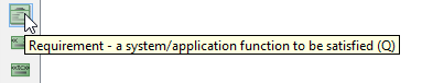
To create a Requirement in a SysML requirement diagram, click the Requirement button on the diagram toolbar and then click on the diagram.
 |
| Create requirement |
Decomposing requirement
To decompose a Requirement in a SysML requirement diagram:
- Move your mouse pointer over the requirement.
- Press on the Resource Catalog button at top right and drag it out.
- Release the mouse button at the place where you want the decomposed requirement to be created.
- Select Containment -> Requirement from Resource Catalog.
- A new requirement will be created and is connected to the source requirement with a containment connector. Enter its name and press Enter to confirm editing.
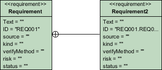
Requirement and Containment created
Inline editing requirement properties
To inline edit the property of a Requirement (e.g. ID), double-click on the property, enter new value and press Enter to confirm.
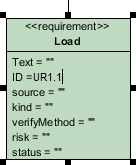 |
| Inline editing Requirement properties |
Editing requirement properties with specification window
You can edit the properties of a requirement through the specification window. To open the window, click on the tiny magnifier icon at the top right of a Requirement shape.
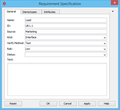 |
| Requirement Specification |
Creating test case and link to requirement
A test case describe the possible scenarios for testing a requirement. To create a Test Case, click the Test Case button on the diagram toolbar and then click on the diagram.
 |
| Create test case |
Move your mouse pointer to the Test Case. Press on the Resource Catalog button at top right and drag it out. Move the mouse pointer over a Requirement and then release the mouse button, a Verify relationship will be created from the Test Case to the Requirement.
 |
| Verify relationship created |
Related Resources
The following resources may help you to learn more about the topic discussed in this page.
| Chapter 14. Requirement diagram | Table of Contents | 2. Customizing requirement types |