How to Draw Class Diagram?
A class diagram is a kind of UML diagram that shows the objects that are required and the relationships between them. Since it provides detailed information about the properties and interfaces of the classes, it can be considered as the main model and regard the other diagrams as supplementary models.
Creating class diagram
Perform the steps below to create a UML class diagram in Visual Paradigm.
- Select Diagram > New from the application toolbar.
- In the New Diagram window, select Class Diagram.
- Click Next.
- Enter the diagram name and description. The Location field enables you to select a model to store the diagram.
- Click OK.
Creating class
To create a class in a class diagram, click Class on the diagram toolbar and then click on the diagram.
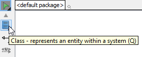 |
| Create class |
A class will be created.
| Class created |
Creating association
To create an associated class in a class diagram:
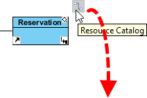
- Move your mouse pointer over the source shape.
- Press on the Resource Catalog button and drag it out.
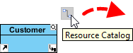
Using Resource Catalog - Release the mouse button at the place where you want the class to be created. If you want to connect to an existing class, drop at that class. Otherwise, drop an the empty space (either at the diagram background or container shape like package).
- If you are connecting to an existing class, select Association from Resource Catalog. If you are creating a new class, select Association -> Class from Resource Catalog. If you want to create an aggregation or composition, select Aggregation -> Class or Composition -> Class instead.
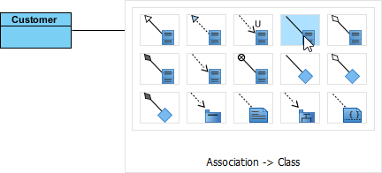
To create a class - If you are creating a new class, you should see the class now and it is connected to the source shape. Enter its name and press Enter to confirm editing.
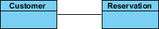
Associated class created
To edit multiplicity of an association end, right-click near the association end, select Multiplicity from the popup menu and then select a multiplicity.
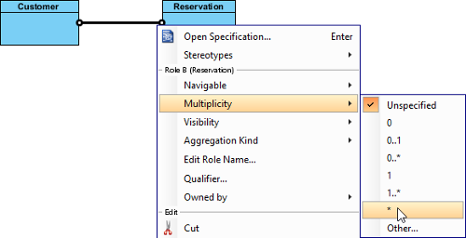 |
| Edit multiplicity |
To show the direction of an association, right click on it and select Presentation Options > Show Direction from the pop-up menu.
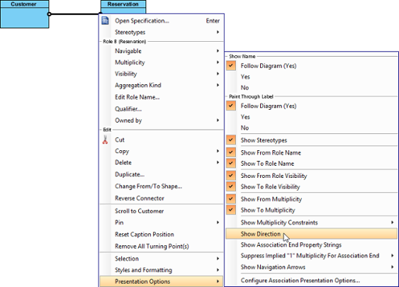 |
| Show direction |
The direction arrow is shown beside the association.
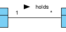 |
| Direction shown |
Creating generalization
To create a subclass:
- Move your mouse pointer over the superclass.
- Press on the Resource Catalog button and drag it out.
Using Resource Catalog - Release the mouse button at the place where you want the subclass to be created. If you want to connect to an existing class, drop at that class. Otherwise, drop an the empty space (either at the diagram background or container shape like package).
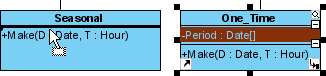
- If you are connecting to an existing class, select Generalization from Resource Catalog. If you are creating a new class, select Generalization -> Class from Resource Catalog.
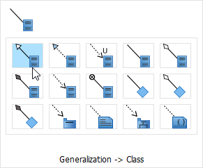
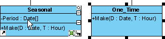
To create a subclass - If you are creating a new class, you should see the class now and it is connected to the source shape with a generalization. Enter its name and press Enter to confirm editing.
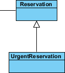
Subclass created
Creating dependency from/to attribute/operation
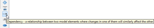
You can also add a dependency from and/or to an attribute or operation in class. To create such a dependency.
- Select Dependency from the diagram toolbar.
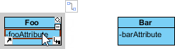
Selecting Dependency - Press on the source shape or a class member.
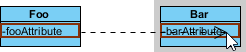
To press on the source operation - Drag to the target shape, or a class member.
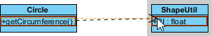
Dragging to target attribute - Release the mouse button to create the dependency.
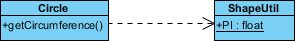
Dependency created between an operation and a member
Creating attribute
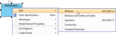
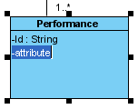
To create attribute, right click the class and select Add > Attribute from the pop-up menu.
 |
| Create attribute |
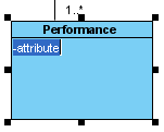
An attribute is created.
 |
| Attribute created |
Creating attribute with enter key
After creating an attribute, press the Enter key, another attribute will be created. This method allows you to create multiple attributes quickly and easily.
 |
| Create attribute with Enter key |
Creating operation
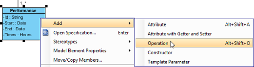
To create operation, right click the class and select Add > Operation from the pop-up menu.
 |
| Create operation |
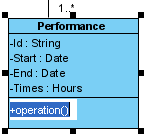
An operation is created.
 |
| Operation created |
Similar to creating attribute, you can press the Enter key to create multiple operations continuously.
Showing just a parameter's type
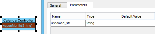
When the name of a parameter starts with "unnamed_", its name will not be displayed in the class shape, leaving the parameter type (if defined).
 |
| Unnamed parameter |
Drag-and-Drop reordering, copying and moving of class members
To reord a class member, select it and drag within the compartment, you will see a thick black line appears to indicate where the class member will be placed.
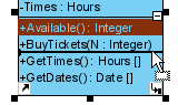 |
| Reorder class member |
Release the mouse button, the class member will be reordered.
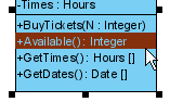 |
| Class member reordered |
To copy a class member, select it and drag to the target class while keep pressing the Ctrl key, you will see a thick black line appears indicating where the class member will be placed. A plus sign is shown beside the mouse cursor indicating this is a copy action.
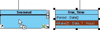 |
| Copy class member |
Release the mouse button, the class member will be copied.
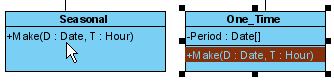 |
| Class member copied |
To move a class member, select it and drag to the target class, you will see a thick black line appears indicating where the class member will be placed. Unlike copy, do not press the Ctrl key when drag, the mouse cursor without the plus sign indicates this is a move action.
 |
| Move class member |
Release the mouse button, the class member will be moved.
 |
| Class member moved |
Selecting all class members
To select all members within a class, you can select any member first, and then press Alt-A to select the rest.
Relating class members
Relationships such as dependency and generic connectors can be added between attribute and operation of classes. To do this:
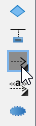
- Select the type of relationship to be created, under the diagram toolbar.
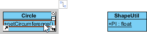
Selecting Dependency - Move the mosue pointer over the source member.
Create a relationship from a class member - Press on it and hold the mouse button.
- Drag to the target member.
Release mouse button on target class member - Release the mouse button to create the connector. While it looks like the connector is connecting the classes but not the members, if you check its specification you can see that the connector is indeed connecting the members.
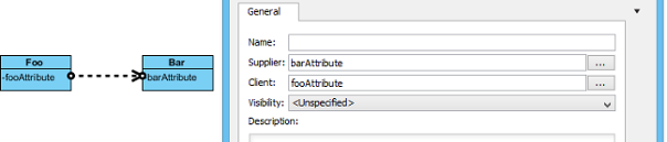
Relationship created
Creating enumeration and adding enumeration literal
An enumeration is a special data type that consists of a pre-defined set of values, known as enumeration literals. Here are some of the common examples:
- Color (RED, GREEN, BLUE)
- Orientation (NORTH, SOUTH, EAST, WEST)
- Switch (ON, OFF)
To create an enumeration in the uml diagram tool, select Enumeration from the diagram toolbar and click on the diagram to create one.
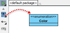 |
| Create an enumeration |
To add an enumeration literal, right click on the enumeration class and select Add > Enumeration Literal from the popup menu.
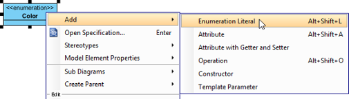 |
| Add an enumeration literal |
Then, enter the name of the literal and confirm editing.
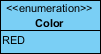 |
| Enumeration literal entered |
Generalization set
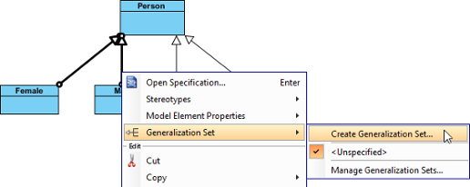
A generalization set defines a particular set of generalization relationships that describe the way
in which a general classifier (or superclass) may be divided using specific subtypes. To define a generalization set, select the generalizations to include, right click and select Generalization set > Create Generalization Set... from the popup menu.
 |
| Create a generalization set |
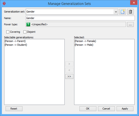
Name the set in the Manage Generalization Sets window, and confirm by pressing OK.
 |
| Name the generalization set |
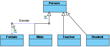
The selected generalizations are grouped. Adjust the connector to make the diagram tidy.
 |
| Adjust connector |
Repeat the steps for other generalizations.
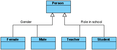 |
| Generalization sets defined |
Defining delegate method for class
When project's programming language is set to be Visual Basic or C#, it is possible to define delegate method for classes. To define delete method, right click on the class and select Stereotypes > Delegate from the pop-up menu.
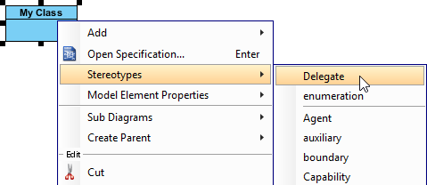 |
| Stereotype class as Delegate |
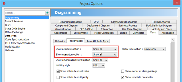
Hiding (and showing) attributes and operations
Per workspace
This applies to new classes that will be created in a project opened in specific workspace. To change the setting:
- Select Window > Project Options from the toolbar to open the Options window.
- Click Diagramming on the list.
- Open the Class tab.
- Click Presentation tab.
- Change the settings for Show attribute option and/or Show operation option.
Show or hide operations
Per diagram
This applies to classes in specific diagram. To change the setting:
- Right click on the class diagram to set the option.
- Select Presentation Options > Attribute Display Options / Operation Display Options from the pop-up menu.
- Select Hide All / Show All / Show Public Only.
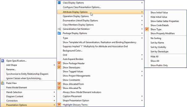
Change the operations' presentation options for classes in diagram
Per class
This applies to specific class. To change the setting:
- Right click on the class to set the option.
- Select Presentation Options > Attributes / Operations from the popup menu.
- Select Hide All / Show All / Show Public Only.
Change the operations' presentation options for a class
For specific attribute/operation
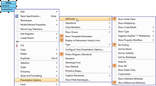
Instead of showing or hiding all members or public members, you may show/hide specific class member per class. To do this:
- Right click on the class to set the option.
- Select Presentation Options > Attributes / Operations > Customized... from the pop-up menu.
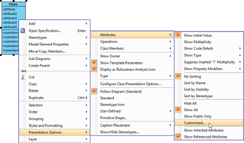
Show or hide specific class member - Select Customized under the drop down menu of Show.
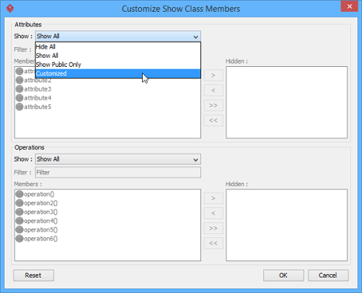
Select Customized in window - Select the member(s) to hide and click > to hide them.
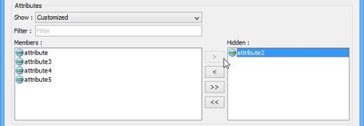
Select attributes to hide - Click OK button to confirm.
Setting initial (default) value for attribute
Initial value can be set to an attribute, indicating the default value of the attribute when the owning object is instantiated. You can give a text value for initial value, or select an attribute of another class. To set initial value to an attribute:
- Open the specification window of attribute by right clicking on the attribute and selecting Open Specification... from the popup menu.
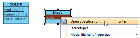
Opening the attribute specification - In the General page of the specification window, enter the initial value in initial value field if it is a text value, or popup the drop down menu to select a public and static field of any class to be the value.
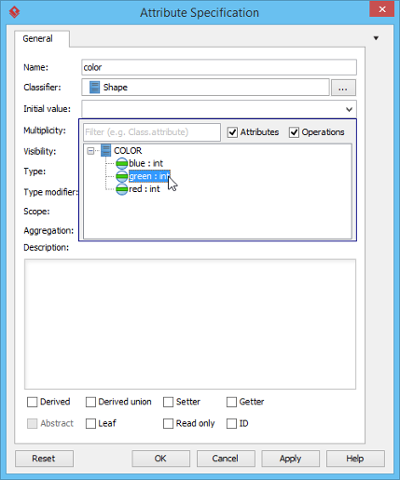
Selecting an initial value NOTE: In order to select the attribute of another class to be the default value, make sure the attribute you want to select is static (i.e. set to be in classifier scope) and is public (so that other classes can access). - Click OK to confirm.
Setting the ownership of association end
Ownership of association ends by an associated class may be indicated by a small dot. To set the ownership, right click at the association end where you want to set ownership, select Owned by in the popup menu, then select either the association or the class at the opposite end. By selecting class, the small dot will be shown.
| Association end with ownership set |
Subsetting on association end
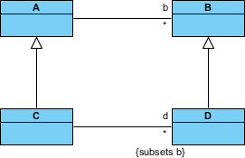
Take a look at the sample below. The subset on d indicates that the collection d, which is an instance of class C, is a subset of the collection b, instance of class A.
 |
| Subsetting on association end |
To define a subset on an association end:
- Right click on the association (where the subset end exist) and select Open Specification... from the popup menu.
- In the General tab, locate the association end where you want to define a subset. Click on ... for the Role property of the association end.
- In the Association End Specification, open the Subsetted Association Ends tab.
- From the list on the left hand side, click on the role you want to define subset for. Click > to select it. If you do not see any role listing there, make sure your model respect the pattern similar to the class diagram above - The class of both association ends are subclasses, and there is an association connecting their superclasses.
- Click OK to confirm and close the Association End Specification window.
- Click OK to confirm and close the Association Specification window.
- Right click on the association end and select Presentation Options > Show Association End Property Strings from the popup menu to show the subset.
Related Resources
The following resources may help you to learn more about the topic discussed in this page.
- What is Class Diagram? - An introductory guide to Class Diagram
- New to Visual Paradigm? We have a lot of UML tutorials written to help you get started with Visual Paradigm
- Visual Paradigm on YouTube
- Visual Paradigm Know-How - Tips and tricks, Q&A, solutions to users' problems
- Contact us if you need any help or have any suggestion
| Chapter 2. Class diagram | Table of Contents | Chapter 3. Sequence diagram |