As a general purpose modeling language, UML provides a stable basis for a wide variety of requirements. It is not defined for specific application domains or for any specific technology. However, in some circumstances, UML is too general and using it involves a considerable amount of effort. In such cases, the use of a language optimized for the given domain and therefore offering special concepts is advantageous.
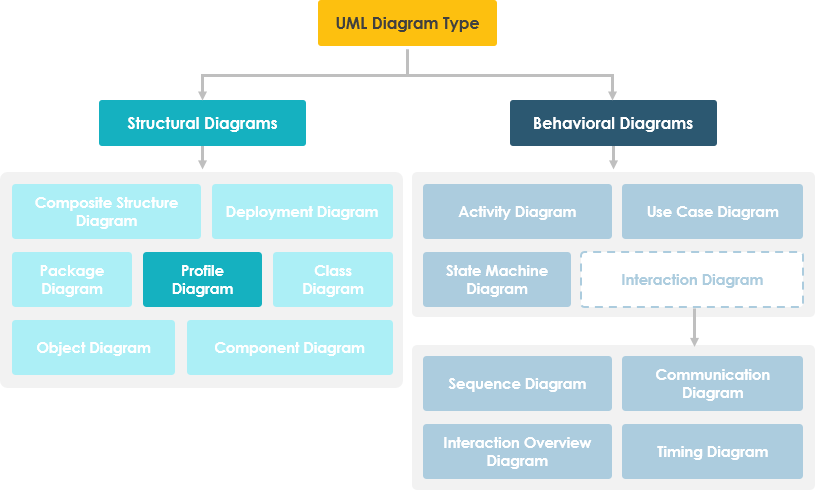
Profile diagram, a kind of structural diagram in the Unified Modeling Language (UML), provides a generic extension mechanism for customizing UML models for particular domains and platforms. Extension mechanisms allow refining standard semantics in strictly additive manner, preventing them from contradicting standard semantics. Profiles are defined using stereotypes, tagged value definitions, and constraints which are applied to specific model elements, like Classes, Attributes, Operations, and Activities. A Profile is a collection of such extensions that collectively customize UML for a particular domain (e.g., aerospace, healthcare, financial) or platform (J2EE, .NET).
Are you looking for a UML tool for learning UML faster, easier and quicker? Visual Paradigm is a UML software that supports all UML diagram types. It is an international award-winning UML modeler, and yet it is easy-to-use and intuitive. Try now.
Download NowProfile diagram is basically an extensibility mechanism that allows you to extend and customize UML by adding new building blocks, creating new properties and specifying new semantics in order to make the language suitable to your specific problem domain.
Profile diagram has three types of extensibility mechanisms:
Stereotypes allow you to increase vocabulary of UML. You can add, create new model elements, derived from existing ones but that have specific properties that are suitable to your problem domain. Stereotypes are used to introduce new building blocks that speak the language of your domain and look primitive. It allows you to introduce new graphical symbols.
For example: When modeling a network you might need to have symbols for <<router>>, <<switches>>, <<hub>> etc. A stereotype allows you to make these things appear as primitive.

Tagged values are used to extend the properties of UML so that you can add additional information in the specification of a model element. It allows you to specify keyword value pairs of a model where keywords are the attributes. Tagged values are graphically rendered as string enclose in brackets.
For Example: Consider a release team responsible for assembling, testing and deployment of a system. In such case it is necessary to keep a track on version and test results of the main subsystem. Tagged values are used to add such info.
Tagged Value can be useful for adding properties to the model for some useful purposes:

They are the properties for specifying semantics or conditions that must be held true at all the time. It allows you to extend the semantics of UML building block by adding new protocols. Graphically a constraint is rendered as string enclose in brackets placed near associated element.
For example: In development of a real time system it is necessary to adorn the model with some necessary information such as response time. A constraint defines a relationship between model elements that must be use {subset} or {xor}. Constraints can be on attributes, derived attributes and associations. It can be attached to one or more model elements shown as a note as well.

As an alternative to creating a new metamodel, you can also extend Extension and modification of the UML metamodel and modify the UML meta-model in accordance with your requirements. In UML we call it lightweight extensions which are based on stereotypes and profiles. UML Profile can be defined in one of the following 3 ways:
The extension mechanism in UML 1.1 is relatively imprecise in the sense that extensions could be made only on the basis of the primitive data type string. UML 2.0 lets you use arbitrary data structures for extended elements, which means that more extensive and more precise model extensions are now possible.
The profiles mechanism is not a first-class extension mechanism. It does NOT allow to:
Profile only allows adaptation or customization of an existing metamodel. In UML 2.0 or above, profiles can also be dynamically combined so that several profiles will be applied at the same time on the same model.

In this example, we can see that a stereotype can extend from one or more metaclasses. This extension relationship is depicted as an arrow with a continuous line and filled arrowhead. The arrow points away from the stereotype to the metaclass.
In the figure below, we define a profile of EJB as a package. The bean itself is extended from component metamodel as an abstract bean. The abstract bean can be concreted as either an Entity Bean or Session Bean. An EJB has two types of remote and home interfaces. An EJB also contains a special kind of artifact called JAR file for storing a collection of Java code.

Stereotypes can be in textual or graphical representation. The icon can also replace the normal class box. For Example: People often use these 3 stereotyped class representations to model the software MVC framework:
Every technical target, i.e. programming language, middleware, library or database is a natural candidate for defining UML profile. For examples:
To use stereotypes in a specific application, you must first integrate the profile that contains the stereotypes. You do this with a dashed arrow than open arrowhead pointing away from the package of the application towards the profile. This arrow is labelled with the keyword <<apply>>.
A profile is applied to another package in order to make the stereotypes in the profile available to that package. The illustration below shows the Network, Telecomms and Software profiles being applied to the ITManagement package.

In the figure below, we define a profile of EJB as a package. The bean itself is extended from component metamodel as an abstract bean. The abstract bean can be concreted as either an Entity Bean or Session Bean. An EJB has two types of remote and home interfaces. An EJB also contains a special kind of artifact called JAR file for storing a collection of Java code.

You've learned what a Profile Diagram is and how to draw a Profile Diagram. It's time to draw a Profile Diagram of your own. Get Visual Paradigm and create your own Profile Diagram with the Profile Diagram tool. It's easy-to-use and intuitive.
Download Now