UML (Unified Modeling Language) Class Diagrams are the architectural blueprints of object-oriented programming. They allow you to visualize the structure of your system—the classes, their attributes, their behaviors, and how they relate to one another—before you write a single line of code.
These elements represent the "things" in your system.
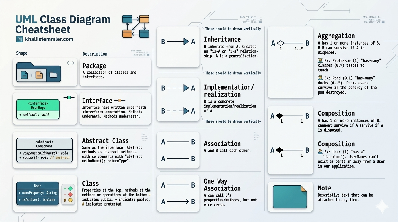
Package: A folder or container used to group related classes and interfaces to keep your code organized.
Class: The fundamental unit. It contains:
Attributes: Data or properties (e.g., name, id).
Methods: Behaviors or functions (e.g., calculateTotal()).
Visibility Modifiers: + (public), - (private), and # (protected).
Interface: A contract that defines what a class must do, but not how. A class "realizes" or implements an interface.
Abstract Class: A template for other classes. You cannot create an instance of an abstract class directly; it must be extended by a concrete class.
Relationships show how your classes interact and depend on each other.
Inheritance: Used for "is-a" relationships (e.g., a Dog is a Animal). The sub-class inherits all attributes and methods from the parent.
Implementation: Used when a class formally signs a contract to implement all methods defined in an Interface.
Association: The most basic relationship. It simply means two classes know about each other and can interact.
One-way Association: Class A knows about Class B, but Class B has no knowledge of Class A.
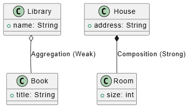
Aggregation ("Weak" Has-A): Class A has a collection of Class B. If Class A is destroyed, Class B continues to exist.
Composition ("Strong" Has-A): Class A creates and owns Class B. If Class A is destroyed, Class B is destroyed with it.
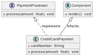
PlantUML allows you to write diagrams as code. Below are examples of how these relationships are structured.
@startuml
interface PaymentProcessor {
  + process(amount: float): void
}

abstract class Component {
  + {abstract} render(): void
}

class CreditCardPayment {
  - cardNumber: String
  + process(amount: float): void
}

PaymentProcessor <|.. CreditCardPayment : implements
Component <|-- CreditCardPayment : inherits
@enduml
@startuml
class Library {
  + name: String
}
class Book {
  + title: String
}
class House {
  + address: String
}
class Room {
  + size: int
}

Library o-- Book : Aggregation (Weak)
House *-- Room : Composition (Strong)
@enduml
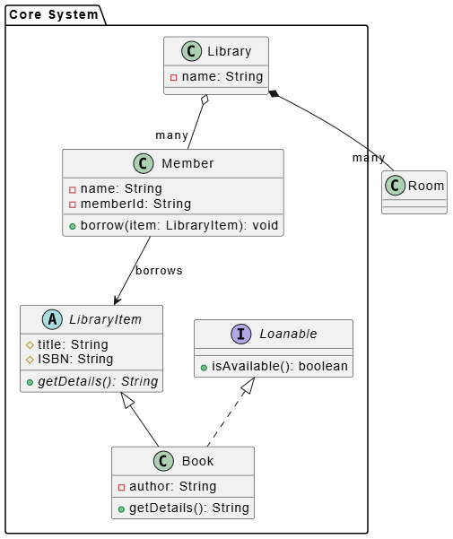
To master UML class diagrams, the best approach is to see how various components interact within a single, cohesive system. Below is a comprehensive example representing a Library Management System.
This system demonstrates the core building blocks: Classes with various visibility levels, Interfaces, Abstract Classes, and the most common Relationships (Inheritance, Realization, Aggregation, and Composition).
You can copy this block into any PlantUML editor to render the diagram.
@startuml
' --- Packages ---
package "Core System" {

    ' --- Abstract Class & Interface ---
    interface Loanable {
        + isAvailable(): boolean
    }

    abstract class LibraryItem {
        # title: String
        # ISBN: String
        + {abstract} getDetails(): String
    }

    ' --- Concrete Classes ---
    class Book {
        - author: String
        + getDetails(): String
    }

    class Member {
        - name: String
        - memberId: String
        + borrow(item: LibraryItem): void
    }

    class Library {
        - name: String
    }
}

' --- Relationships ---
' Inheritance
LibraryItem <|-- Book

' Implementation
Loanable <|.. Book

' Composition: A Library owns Rooms; if Library is gone, Rooms cease to exist
Library *-- "many" Room

' Aggregation: A Library has Members; if Library is gone, Members still exist
Library o-- "many" Member

' Association
Member --> LibraryItem : borrows
@enduml
By analyzing the code above, you can see how the syntax covers the requirements of the cheat sheet:
Defining Elements:
interface and abstract class: Used to define contracts and base templates for Book.
Visibility Modifiers: Notice the use of - (private), # (protected), and + (public) inside the classes to define how data is accessed.
Defining Relationships:
Inheritance (<|--): Used because a Book is a LibraryItem.
Realization (<|..): Used because Book implements the Loanable interface.
Composition (*--): The library strictly owns the rooms (they cannot exist outside the library).
Aggregation (o--): Members are associated with the library but exist independently of it.
One-way Association (-->): A Member knows about the LibraryItem they are borrowing, but the item does not necessarily need to know about the member.
Using this combined view allows you to see the "big picture" of your software architecture. Instead of viewing classes in isolation, this layout helps you understand how memory might be managed (Composition vs. Aggregation) and how your code should be organized into modules (Packages).
Are you ready to try mapping out your own project, or would you like to refine the components of this library example further?
Keep it simple: Don't try to document every single tiny detail at first. Focus on the core relationships.
Use Notes: The "Note" shape (a rectangle with a dog-eared corner) is your best friend. If a relationship is complex, attach a note to explain it.
Read Vertically: When drawing, put parent classes (for inheritance) at the top and sub-classes at the bottom to make the flow intuitive.
Version Control: By using tools like PlantUML, you can track changes to your diagrams just like you track your application code.