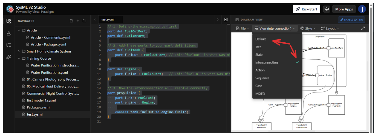
SysML v2 introduces a paradigm shift in systems engineering by prioritizing textual notation as the primary source of truth, with diagrams serving as dynamic visualizations of that text. This guide breaks down the core philosophy of "Definition before Usage," analyzes the provided textual model, and explores the strategic differences between the Default View and the Interconnection View.
In SysML v2, you must define the "blueprints" before you can build the "house." The provided textual notation illustrates this hierarchy perfectly:
Port Definitions (port def): These define the interface type (e.g., FuelInPort). They specify the "shape" of the connection—what kind of data or matter can pass through.
Part Definitions (part def): These are the component blueprints. By nesting ports inside a definition (e.g., adding fuelOut inside FuelTank), you establish that every instance of a Fuel Tank will inherently possess that output port.
Part Usage (part propulsion): This is the system assembly. Here, you instantiate the definitions (creating specific instances named tank and engine) and create a topological connection (connect tank.fuelOut to engine.fuelIn).
While the text remains the same, SysML v2 tools allow you to visualize this data in different ways depending on your engineering goal.
Focus: Topology, Flow, and Interaction.
Goal: To answer "How do these specific instances interact to perform a function?"
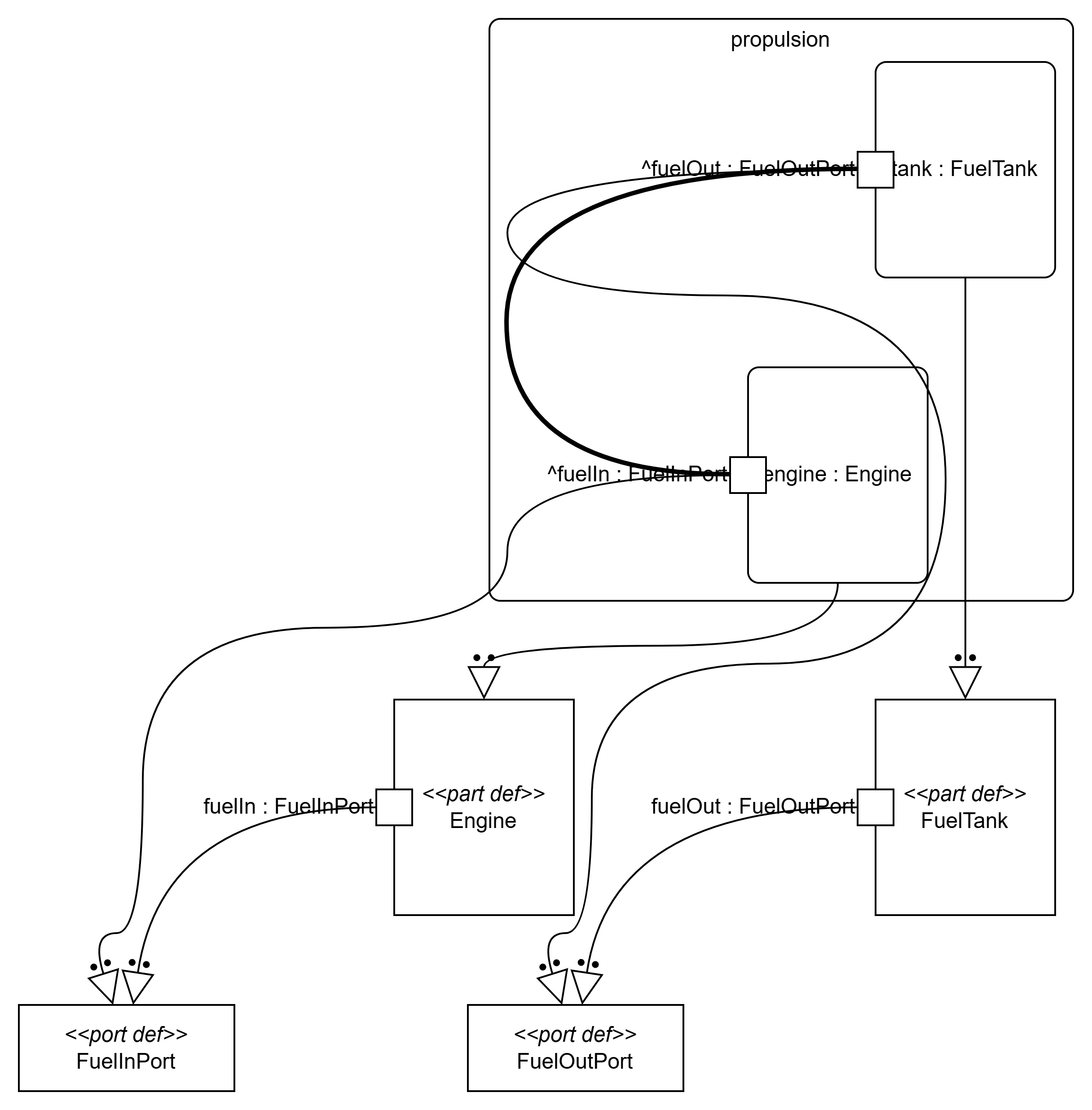
This view, represented in Figure 1, looks inside the propulsion assembly. It ignores the library definitions and focuses purely on the "wiring" of the current system.
Key Features in Figure 1:
The Boundary: The large box labeled propulsion represents the system boundary.
Instances: Inside, we see specific instances: tank : FuelTank and engine : Engine. The colon indicates that these are usages of the definitions.
The Connector: The curved line connecting the two parts is the physical or logical link.
Visual Emphasis: Note the thick, bold line connecting ^fuelOut to ^fuelIn. In SysML v2 visualization, bolding often highlights the active flow or the primary functional path (the movement of fuel) versus the structural hierarchy.
[Insert Image 1 Here: The Interconnection View showing the
propulsionblock with internal connections]
Figure 1: The Interconnection View highlights the topology. We see thetankinstance connected to theengineinstance via a bold connector, representing the flow of fuel.
Focus: Taxonomy, Composition, and Library Management.
Goal: To answer "How is this system defined, and what is it made of?"
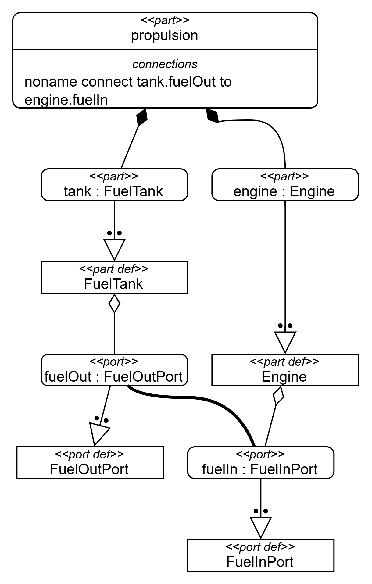
This view, represented in Figure 2, exposes the underlying structure. It shows the relationship between the high-level assembly and the low-level definitions.
Key Features in Figure 2:
Composition: The top block <<part>> propulsion has composition relationships (filled diamonds) connecting to tank and engine. This tells us the propulsion system is composed of these parts.
Textual Transparency: The propulsion block explicitly lists the connection logic: noname connect tank.fuelOut to engine.fuelIn.
Instantiation/Realization: The arrows pointing down to <<part def>> FuelTank and <<part def>> Engine show that the parts above are instances of these definitions.
Port Definitions: At the bottom, we see the raw definitions (<<port def>>) that establish the interface standards.
[Insert Image 2 Here: The Default View showing the hierarchy from
propulsiondown topart defandport def]
Figure 2: The Default View reveals the hierarchy. It shows how thepropulsionpart is composed of instances that specialize the base definitions (FuelTank,Engine) and their ports.
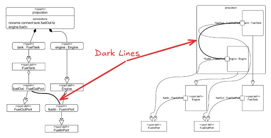
In SysML v2 diagrams, line weight is a critical semantic indicator.
| Feature | Light Line (Thin) | Dark Line (Bold/Thick) |
|---|---|---|
| Concept | Structural Connection (Connector) | Flow / Succession |
| Meaning | "These two ports are linked." (The pipe exists). | "Something is moving." (Fuel is flowing). |
| Analogy | The physical copper wire. | The electricity running through the wire. |
| Usage | Use for Interface Control Documents (ICD) or physical layout. | Use for Functional Analysis or tracing active signals. |
In Figure 1, the connector between the tank and engine is drawn with a bold line. This draws the architect's eye immediately to the primary functional path—the transit of fuel—distinguishing it from the static structural relationships shown in the rest of the diagram.
| Feature | Default View (Figure 2) | Interconnection View (Figure 1) |
|---|---|---|
| Primary Focus | Definition & Structure | Interaction & Flow |
| Main Elements | part def, port def, Composition |
part (usage), connect, Flows |
| Relationship | "Is a" or "Contains" (Hierarchy) | "Flows to" (Topology) |
| Level of Abstraction | High (The Blueprint / Library) | Contextual (The Assembly / Instance) |
| SysML v1 Equivalent | Block Definition Diagram (bdd) | Internal Block Diagram (ibd) |
Use the Default View (Figure 2) when you are designing the library. You are creating reusable component definitions (FuelTank) that will be used across multiple projects. You are defining the "LEGO bricks."
Use the Interconnection View (Figure 1) when you are defining system logic. You need to show how specific parts (tank and engine) work together to achieve a requirement (like "Provide Propulsion"). You are showing how you've snapped the bricks together to build a "Spaceship."