
Based on the presentation by Simon Field, Principal Architect, Bank of England (BCS EASG Conference, Sept 2022)
The C4 model is a lightweight, structured approach to diagramming software architecture that organizes system design into four clear layers of abstraction. When properly embedded into an Enterprise Architecture (EA) metamodel, it acts as the "glue" that aligns business strategy, solution design, and software implementation.
This guide combines theoretical foundations with a complete, practical case study—the Internet Banking System—to show you exactly how to implement the C4 model at every level, using valid, renderable PlantUML code.
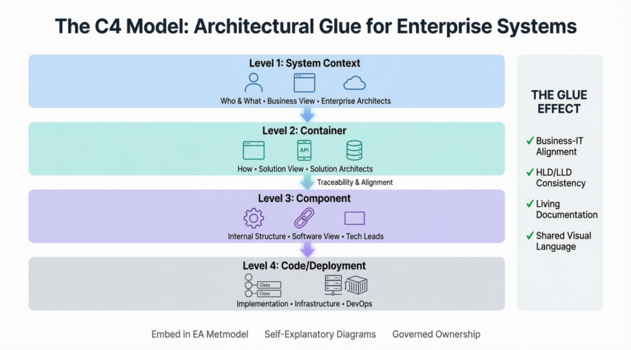
Developed by Simon Brown as a pragmatic approach to software architecture diagramming.
Model & diagramming language agnostic: Can be implemented in any modeling tool (e.g., Sparx Enterprise Architect, Draw.io, Structurizr, PlantUML).
Focuses on hierarchical clarity and self-explanatory visuals.
Not a complete architecture modeling solution.
Does not replace specialized artifacts for:
Data architecture & data flows
Customer journey mapping
Business process modeling or workflow orchestration
It is a structural visualization framework, not a governance methodology.
Provides a consistent, scalable way to transition between abstraction levels without losing context.
Enables architects, developers, and business stakeholders to speak a shared visual language.
Supports traceability from enterprise capabilities down to deployment infrastructure.
The C4 model structures architecture into four progressive layers. Below, each layer is explained alongside executable PlantUML code for our Internet Banking System case study.
| Level | Name | Focus | Primary Audience | Key Elements |
|---|---|---|---|---|
| Level 1 | System Context | What & Who (Business/Enterprise view) | Business stakeholders, Enterprise Architects | People, external software systems, high-level interactions |
| Level 2 | Container | How (Solution/Software view) | Solution Architects, Development Leads | Executable/deployable units (web apps, APIs, databases), technology choices |
| Level 3 | Component | Internal Structure (Software view) | Software Architects, Senior Developers | Logical components within containers (controllers, services, facades) |
| Level 4 | Code / Deployment | Runtime & Infrastructure | DevOps, Infrastructure Engineers, SREs | Classes, interfaces, deployment nodes, networks, scaling |
Shows the scope of the system and how users and external systems interact with it.
Purpose: Answer "What is this system and who uses it?"
Key Elements:
Personal Banking Customer (Person)
Internet Banking System (Software System)
E-mail System (External System)
Mainframe Banking System (External System)
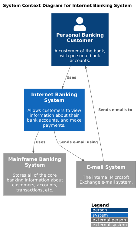
@startuml
!include https://raw.githubusercontent.com/plantuml-stdlib/C4-PlantUML/master/C4_Context.puml

LAYOUT_WITH_LEGEND()
title System Context Diagram for Internet Banking System

Person(customer, "Personal Banking Customer", "A customer of the bank, with personal bank accounts.")
System(bankingSystem, "Internet Banking System", "Allows customers to view information about their bank accounts, and make payments.")
System_Ext(mailSystem, "E-mail System", "The internal Microsoft Exchange e-mail system.")
System_Ext(mainframe, "Mainframe Banking System", "Stores all of the core banking information about customers, accounts, transactions, etc.")

Rel(customer, bankingSystem, "Uses")
Rel_Back(customer, mailSystem, "Sends e-mails to")
Rel(bankingSystem, mailSystem, "Sends e-mail using")
Rel(bankingSystem, mainframe, "Uses")
@enduml
Enterprise Alignment Tip: Replace generic Person with enterprise role types like Partner Role or Resource Role to align with BPMN and business architecture standards.
Zooms into the system boundary, showing high-level technology building blocks.
Purpose: Answer "How is the system structured at a deployable unit level?"
Key Elements:
Web Application (Java/Spring MVC)
Single-Page Application (JavaScript/Angular)
Mobile App (Xamarin)
API Application (Java/Spring Boot)
Database (Relational)
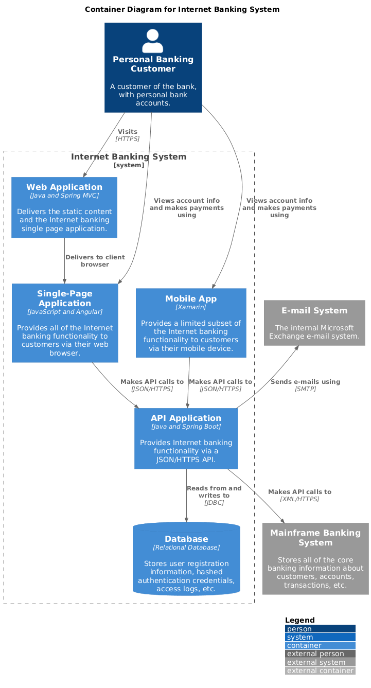
@startuml
!include https://raw.githubusercontent.com/plantuml-stdlib/C4-PlantUML/master/C4_Container.puml

LAYOUT_WITH_LEGEND()
title Container Diagram for Internet Banking System

Person(customer, "Personal Banking Customer", "A customer of the bank, with personal bank accounts.")
System_Ext(mailSystem, "E-mail System", "The internal Microsoft Exchange e-mail system.")
System_Ext(mainframe, "Mainframe Banking System", "Stores all of the core banking information about customers, accounts, transactions, etc.")

System_Boundary(c1, "Internet Banking System") {
    Container(webApp, "Web Application", "Java and Spring MVC", "Delivers the static content and the Internet banking single page application.")
    Container(spa, "Single-Page Application", "JavaScript and Angular", "Provides all of the Internet banking functionality to customers via their web browser.")
    Container(mobileApp, "Mobile App", "Xamarin", "Provides a limited subset of the Internet banking functionality to customers via their mobile device.")
    ContainerDb(database, "Database", "Relational Database", "Stores user registration information, hashed authentication credentials, access logs, etc.")
    Container(apiApp, "API Application", "Java and Spring Boot", "Provides Internet banking functionality via a JSON/HTTPS API.")
}

Rel(customer, webApp, "Visits", "HTTPS")
Rel(customer, spa, "Views account info and makes payments using")
Rel(customer, mobileApp, "Views account info and makes payments using")

Rel(webApp, spa, "Delivers to client browser")
Rel(spa, apiApp, "Makes API calls to", "JSON/HTTPS")
Rel(mobileApp, apiApp, "Makes API calls to", "JSON/HTTPS")

Rel(apiApp, database, "Reads from and writes to", "JDBC")
Rel_Back(mailSystem, apiApp, "Sends e-mails using", "SMTP")
Rel(apiApp, mainframe, "Makes API calls to", "XML/HTTPS")
@enduml
Metamodel Integration: Add Deployed on relationships to link containers to infrastructure platforms (e.g., Kubernetes, AWS EC2).
Zooms into the API Application container to show its internal logical components.
Purpose: Answer "What are the internal building blocks and how do they interact?"
Key Elements:
Sign In Controller (Spring MVC RestController)
Account Controller (Spring MVC RestController)
Security Component (Spring Bean)
Mainframe Banking System Facade (Spring Bean)
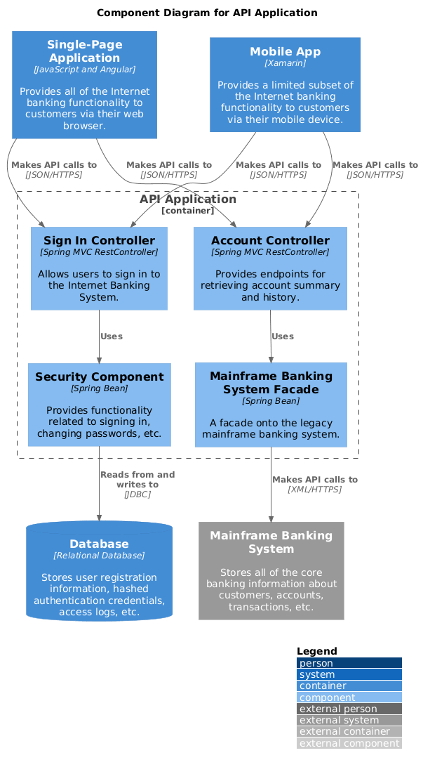
@startuml
!include https://raw.githubusercontent.com/plantuml-stdlib/C4-PlantUML/master/C4_Component.puml

LAYOUT_WITH_LEGEND()
title Component Diagram for API Application

Container(spa, "Single-Page Application", "JavaScript and Angular", "Provides all of the Internet banking functionality to customers via their web browser.")
Container(mobileApp, "Mobile App", "Xamarin", "Provides a limited subset of the Internet banking functionality to customers via their mobile device.")
ContainerDb(database, "Database", "Relational Database", "Stores user registration information, hashed authentication credentials, access logs, etc.")
System_Ext(mainframe, "Mainframe Banking System", "Stores all of the core banking information about customers, accounts, transactions, etc.")

Container_Boundary(api, "API Application") {
    Component(signinController, "Sign In Controller", "Spring MVC RestController", "Allows users to sign in to the Internet Banking System.")
    Component(accountsController, "Account Controller", "Spring MVC RestController", "Provides endpoints for retrieving account summary and history.")
    Component(securityComponent, "Security Component", "Spring Bean", "Provides functionality related to signing in, changing passwords, etc.")
    Component(mainframeFacade, "Mainframe Banking System Facade", "Spring Bean", "A facade onto the legacy mainframe banking system.")

    Rel(spa, signinController, "Makes API calls to", "JSON/HTTPS")
    Rel(spa, accountsController, "Makes API calls to", "JSON/HTTPS")
    Rel(mobileApp, signinController, "Makes API calls to", "JSON/HTTPS")
    Rel(mobileApp, accountsController, "Makes API calls to", "JSON/HTTPS")

    Rel(signinController, securityComponent, "Uses")
    Rel(accountsController, mainframeFacade, "Uses")
    Rel(securityComponent, database, "Reads from and writes to", "JDBC")
    Rel(mainframeFacade, mainframe, "Makes API calls to", "XML/HTTPS")
}
@enduml
Governance Tip: Enforce that component diagrams are owned by Tech Leads and updated during sprint planning or refactoring cycles.
Shows the code structure inside the Account Controller—interfaces, implementations, and dependencies.
Purpose: Answer "How is this component implemented in code?"
Key Elements:
IAccountController interface
AccountController implementation
IMainframeFacade abstraction
MainframeBankingSystemFacade concrete class
AccountSummary domain object
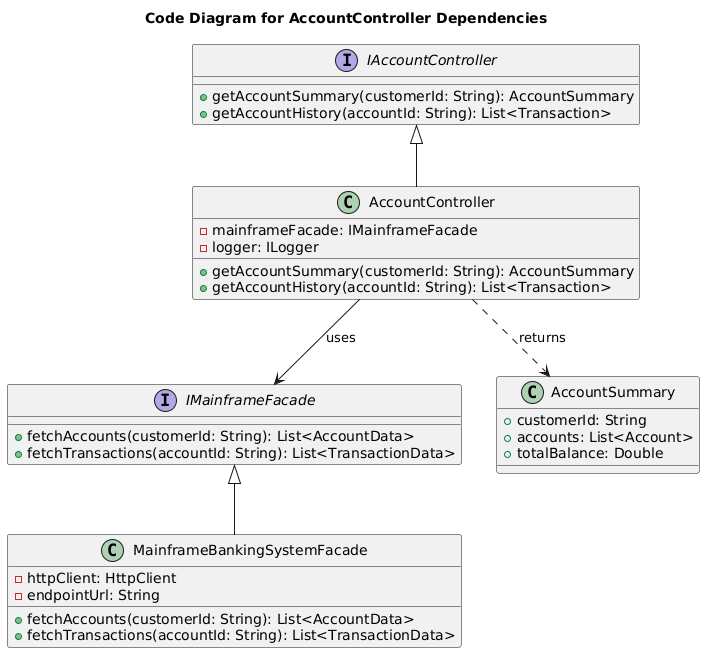
@startuml
title Code Diagram for AccountController Dependencies

interface IAccountController {
    +getAccountSummary(customerId: String): AccountSummary
    +getAccountHistory(accountId: String): List<Transaction>
}

class AccountController {
    -mainframeFacade: IMainframeFacade
    -logger: ILogger
    +getAccountSummary(customerId: String): AccountSummary
    +getAccountHistory(accountId: String): List<Transaction>
}

interface IMainframeFacade {
    +fetchAccounts(customerId: String): List<AccountData>
    +fetchTransactions(accountId: String): List<TransactionData>
}

class MainframeBankingSystemFacade {
    -httpClient: HttpClient
    -endpointUrl: String
    +fetchAccounts(customerId: String): List<AccountData>
    +fetchTransactions(accountId: String): List<TransactionData>
}

class AccountSummary {
    +customerId: String
    +accounts: List<Account>
    +totalBalance: Double
}

IAccountController <|-- AccountController
AccountController --> IMainframeFacade : uses
IMainframeFacade <|-- MainframeBankingSystemFacade
AccountController ..> AccountSummary : returns
@enduml
⚠️ Note: Level 4 diagrams are optional and should only be created for complex or critical components. Over-diagramming at this level creates maintenance overhead.
The C4 model is not a silver bullet, but it is a highly effective structural framework for bringing clarity, consistency, and traceability to enterprise architecture. By embedding it into a formal EA metamodel and using practical, renderable diagrams like those in our Internet Banking System case study, organizations can:
✅ Bridge the gap between business strategy and technical implementation
✅ Prevent HLD/LLD divergence through hierarchical validation
✅ Maintain living, self-explanatory architecture documentation
✅ Enable cross-domain collaboration with a shared visual language
Success requires:
Disciplined governance and clear ownership per layer
Strict adherence to the Self-Explanatory Diagram Standard
Integration with existing EA frameworks and tooling
Regular audits and updates tied to delivery cycles
When implemented correctly, C4 becomes the foundational "glue" that aligns enterprise, business, solution, and software architectures into a cohesive, maintainable whole.
C4 Diagram Tool & Modeling Software: Comprehensive overview of Visual Paradigm's dedicated C4 modeling capabilities, including templates, symbols, and integration features for software architecture documentation.
AI Diagram Generator: Complete C4 Model Support : Release announcement detailing how Visual Paradigm's AI tools now support end-to-end C4 model generation across all abstraction levels.
AI Diagram Generator Release Notes: Technical documentation and feature highlights for the AI-powered diagram generation engine integrated into Visual Paradigm.
AI-Powered C4 PlantUML Studio: Specialized tool description for converting natural language requirements into version-controllable PlantUML code for C4 diagrams.
Visual Paradigm AI Platform: Central hub for Visual Paradigm's suite of AI-assisted modeling, diagramming, and documentation tools.
AI Chatbot for Diagram Generation: Overview of the conversational AI interface that allows users to create and refine diagrams using natural language commands.
AI-Powered C4 PlantUML Markdown Editor: Feature release introducing markdown-based editing workflows for C4 diagrams with AI assistance.
AI Chatbot Tool: Dedicated page for the AI chatbot interface used for interactive diagram creation and refinement.
Use Case to Activity Diagram Feature: Documentation of Visual Paradigm's feature for transforming use case models into activity diagrams, supporting broader architectural workflows.
C4 Model Tool in Visual Paradigm Online: Browser-based C4 modeling capabilities including real-time collaboration, symbol libraries, and cloud synchronization.
C4 Diagram Solution: Enterprise-focused solution page highlighting how Visual Paradigm's C4 tools support large-scale architecture initiatives.
What is C4 Model?: Educational blog post explaining the fundamentals, benefits, and practical applications of the C4 modeling methodology.

