
The Unified Modeling Language (UML) is the industry standard for visualizing the architecture of a software system. However, a common pitfall in system design is treating structural models (the "nouns") and behavioral models (the "verbs") as isolated artifacts. In reality, a robust software model requires a seamless integration of both. The structural building blocks define what the system is, while the behavioral building blocks define how it works over time.
This guide explores the critical intersections where UML's structural and behavioral elements connect. By understanding these semantic links, architects and developers can create cohesive, comprehensive models that accurately reflect both the static architecture and the dynamic execution of a system.
Before diving into the connections, it is essential to define the two primary categories of UML building blocks:
Structural Building Blocks (The "Nouns"): These represent the static, time-independent parts of a system. They define the architecture and the physical or logical entities. Examples include Classes, Objects, Interfaces, Components, Nodes, and Collaborations.
Behavioral Building Blocks (The "Verbs"): These represent the dynamic, time-dependent parts of a system. They define how elements interact, change state, and execute over time. Examples include Interactions, State Machines, and Activities.
The true power of UML is unlocked when these two dimensions are semantically connected, ensuring that the dynamic behavior is always grounded in a valid static structure.
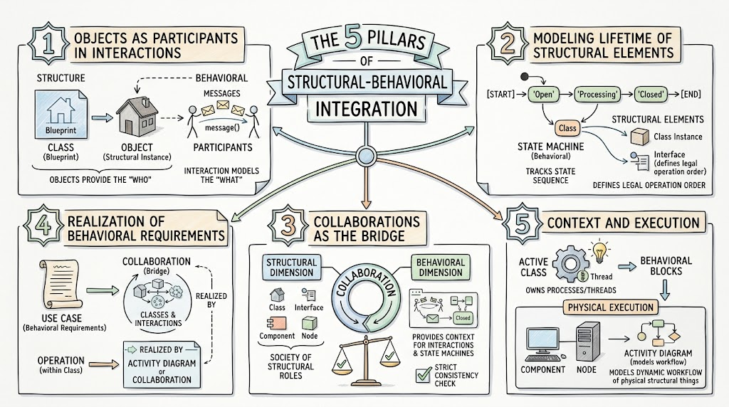
Interactions are the primary behavioral mechanism for modeling dynamic control flow. However, an interaction cannot exist in a vacuum; it requires structural participants.
The Connection: While a Class (structural) defines a blueprint, an Object (structural instance) acts as the actual participant in an Interaction (behavioral). The interaction models the dynamic flow of control—messages passed from object to object—to accomplish a specific task. The structural objects provide the "who," and the interaction provides the "what they are doing."
Systems are not static; their components change states in response to internal or external events.
The Connection: State machines (behavioral) are used to specify the lifecycle behavior of individual structural elements.
You can attach a state machine to a Class or a Collaboration to track the sequence of states an instance goes through.
You can attach a state machine to an Interface to strictly define the legal partial ordering of its operations (e.g., an open() operation must occur before a close() operation).
A Collaboration is a unique, dual-natured building block that acts as the ultimate bridge between structure and behavior.
Structural Dimension: It defines a "society" of structural roles, referencing specific classes, interfaces, components, and nodes that must work together.
Behavioral Dimension: It provides the exact context for interactions and state machines to occur.
Consistency Check: The behavioral parts of a collaboration (like interaction diagrams) must be strictly consistent with its structural parts (like class diagrams). For example, every object participating in the collaboration's interaction must be an instance of one of the classes defined in its structural part.
High-level behavioral requirements must eventually be grounded in structural implementations.
Use Cases: A Use Case describes a set of sequences of actions (behavioral requirements). It is typically realized by a Collaboration (the structural/behavioral bridge) that defines the specific society of classes and their interactions required to fulfill that use case.
Operations: An Operation defined within a structural Class can be realized by a behavioral Collaboration or an Activity Diagram to visually map out its internal algorithmic implementation.
Behavioral blocks never execute in thin air; they always require a structural context to run within.
Active Classes: These are special structural elements that own the processes or threads (behavioral) that initiate dynamic control activity.
Physical Execution: Activity diagrams (behavioral) can be used to model the dynamic workflow of physical structural things like Components and Nodes, showing how software and hardware execute in tandem.
To visualize these concepts, below are PlantUML examples demonstrating how structural and behavioral elements integrate in practice.
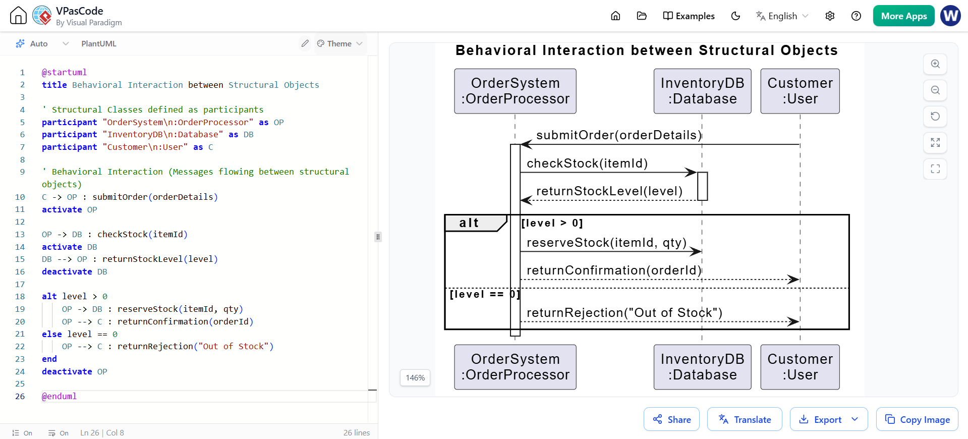
This Sequence Diagram shows structural Objects (instances of structural Classes) exchanging behavioral Messages to fulfill an interaction.
@startuml
title Behavioral Interaction between Structural Objects

' Structural Classes defined as participants
participant "OrderSystem\n:OrderProcessor" as OP
participant "InventoryDB\n:Database" as DB
participant "Customer\n:User" as C

' Behavioral Interaction (Messages flowing between structural objects)
C -> OP : submitOrder(orderDetails)
activate OP

OP -> DB : checkStock(itemId)
activate DB
DB --> OP : returnStockLevel(level)
deactivate DB

alt level > 0
    OP -> DB : reserveStock(itemId, qty)
    OP --> C : returnConfirmation(orderId)
else level == 0
    OP --> C : returnRejection("Out of Stock")
end
deactivate OP

@enduml
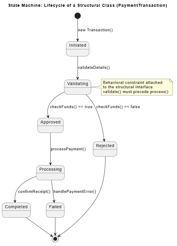
This State Machine Diagram defines the behavioral lifecycle of a structural Class (PaymentTransaction), ensuring operations follow a legal partial ordering.
@startuml
title State Machine: Lifecycle of a Structural Class (PaymentTransaction)

[*] --> Initiated : new Transaction()

Initiated --> Validating : validateDetails()
Validating --> Approved : checkFunds() == true
Validating --> Rejected : checkFunds() == false

Approved --> Processing : processPayment()
Processing --> Completed : confirmReceipt()
Processing --> Failed : handlePaymentError()

Rejected --> [*]
Failed --> [*]
Completed --> [*]

note right of Validating
  Behavioral constraint attached
  to the structural Interface:
  validate() must precede process()
end note

@enduml
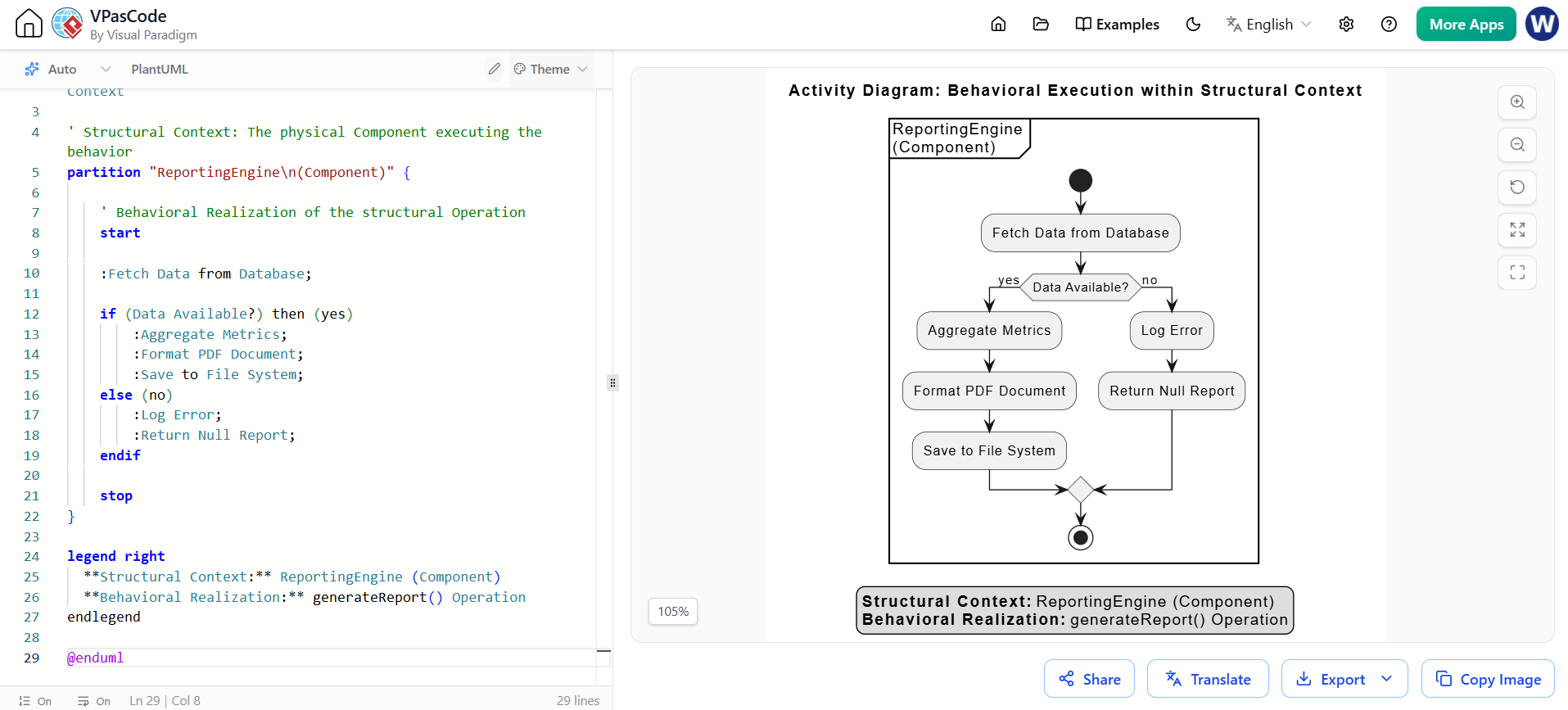
This Activity Diagram illustrates the behavioral realization of a structural Operation (generateReport), executed within the structural context of a physical Component (ReportingEngine).
@startuml
title Activity Diagram: Behavioral Execution within Structural Context

' Structural Context: The physical Component executing the behavior
partition "ReportingEngine\n(Component)" {

    ' Behavioral Realization of the structural Operation
    start

    :Fetch Data from Database;

    if (Data Available?) then (yes)
        :Aggregate Metrics;
        :Format PDF Document;
        :Save to File System;
    else (no)
        :Log Error;
        :Return Null Report;
    endif

    stop
}

legend right
  **Structural Context:** ReportingEngine (Component)
  **Behavioral Realization:** generateReport() Operation
endlegend

@enduml
Modeling a software system requires more than just drawing class diagrams or sketching out use cases in isolation. The true essence of UML lies in the semantic connections between its structural building blocks (the nouns) and its behavioral building blocks (the verbs).
By ensuring that objects actively participate in interactions, tracking the lifecycles of classes via state machines, utilizing collaborations as a bridging mechanism, realizing high-level requirements through structural implementations, and grounding all activities within a physical or logical context, architects can create a unified, unambiguous model. Mastering this integration ensures that your system's design is not only structurally sound but also dynamically viable, leading to more robust, maintainable, and successful software implementations.

