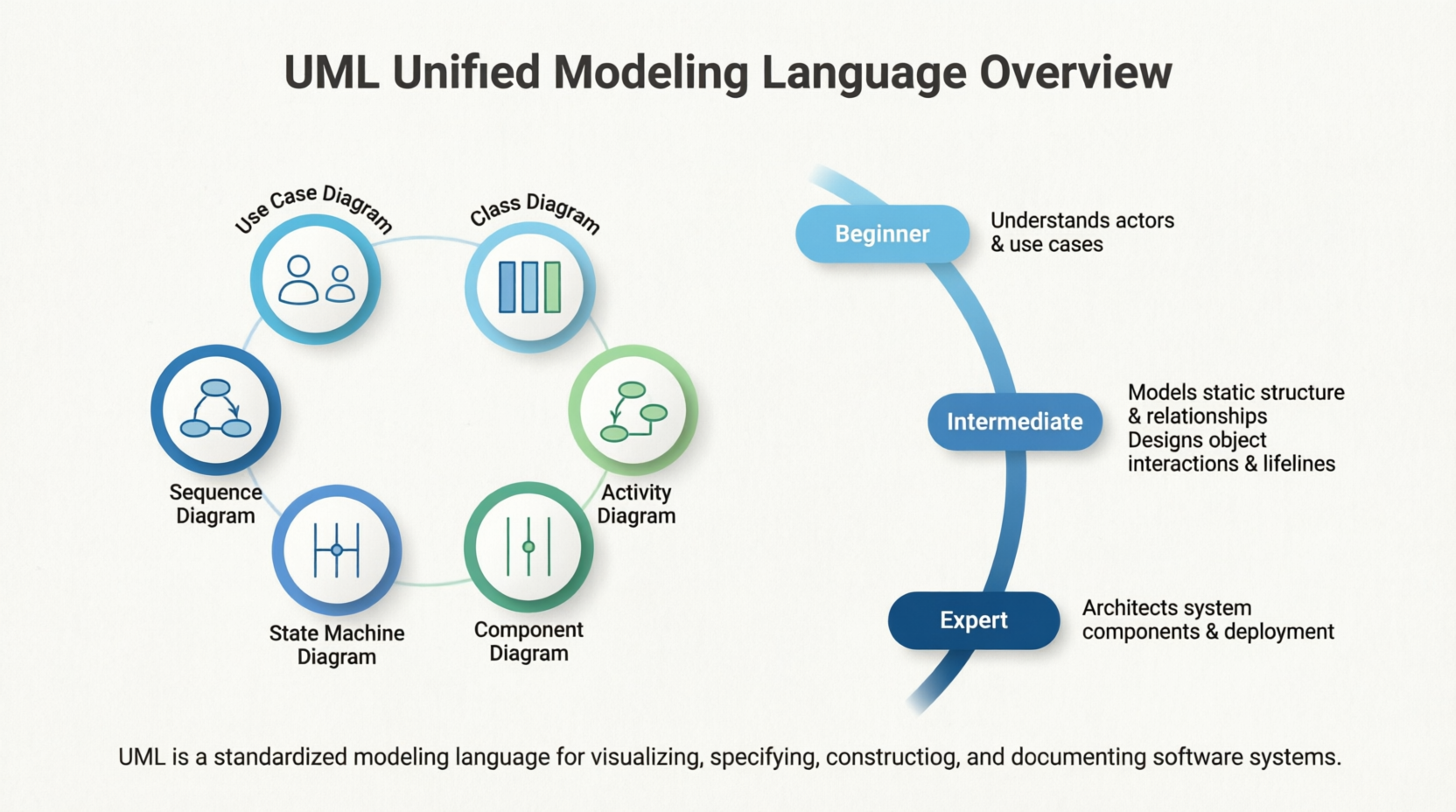
Unified Modeling Language (UML) is the industry-standard visual modeling language for specifying, visualizing, constructing, and documenting the artifacts of software systems (and increasingly other systems like business processes or hardware-software integrations). Created by Grady Booch, James Rumbaugh, and Ivar Jacobson in the mid-1990s and standardized by the Object Management Group (OMG), UML provides a common "blueprint" language that reduces miscommunication between stakeholders, developers, architects, and testers.
This guide takes you from zero knowledge to ninja-level proficiency. You'll learn why UML matters, the core diagram types with key concepts, practical examples, notation rules, best practices, and advanced usage.
Communication: A single class diagram can replace pages of ambiguous text.
Analysis & Design: Catch design flaws early (before coding).
Documentation: Living blueprints that evolve with the system.
Agile & Modern Contexts: Even in iterative development, lightweight UML (e.g., just key sequence or class diagrams) accelerates onboarding and refactoring.
Career Advantage: Essential for software architects, system analysts, technical leads, and anyone working with enterprise or complex systems.
Core Principles:
UML is not a programming language or methodology — it's a notation.
Focus on abstraction and readability over perfection.
Use the right diagram for the right audience (high-level for stakeholders, detailed for developers).
Model Elements:
Classifiers: Classes, interfaces, use cases, actors, components, etc.
Relationships: Association, aggregation, composition, generalization (inheritance), dependency, realization.
Multiplicity: 1, 0..1, 0.., 1.., etc.
Stereotypes: <>, <>, etc., for extensions.
Notes & Constraints: Text explanations or {constraints}.
Structural vs. Behavioral Diagrams:
Structural: Show "what" exists (static view).
Behavioral: Show "how" it works over time (dynamic view).
Views:
Logical View, Process View, Implementation View, Deployment View, Use Case View (the "4+1" architectural view model).
Purpose: Capture functional requirements from the user's perspective.
Key Elements:
Actor (stick figure): User, external system, or role.
Use Case (oval): A goal or functionality (e.g., "Login").
Relationships: Include (mandatory sub-behavior), Extend (optional), Generalization.
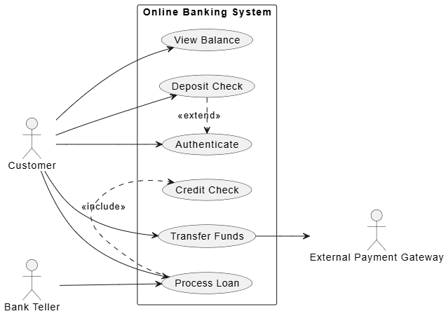
Example – Online Banking System:
Actors: Customer, Bank Teller, External Payment Gateway.
Use Cases: Authenticate, Transfer Funds, View Balance, Deposit Check (extends Authenticate), Process Loan (includes Credit Check).
@startuml
left to right direction
skinparam packageStyle rectangle

actor "Customer" as customer
actor "Bank Teller" as teller
actor "External Payment Gateway" as gateway

rectangle "Online Banking System" {
usecase "Authenticate" as authenticate
usecase "Transfer Funds" as transfer
usecase "View Balance" as view
usecase "Deposit Check" as deposit
usecase "Process Loan" as loan
usecase "Credit Check" as credit
}

customer --> authenticate
customer --> transfer
customer --> view
customer --> deposit
customer --> loan

teller --> loan

deposit .> authenticate : <<extend>>
loan .> credit : <<include>>

transfer --> gateway
@endumlVisual Tip: Keep it simple — avoid clutter. One diagram per major subsystem.
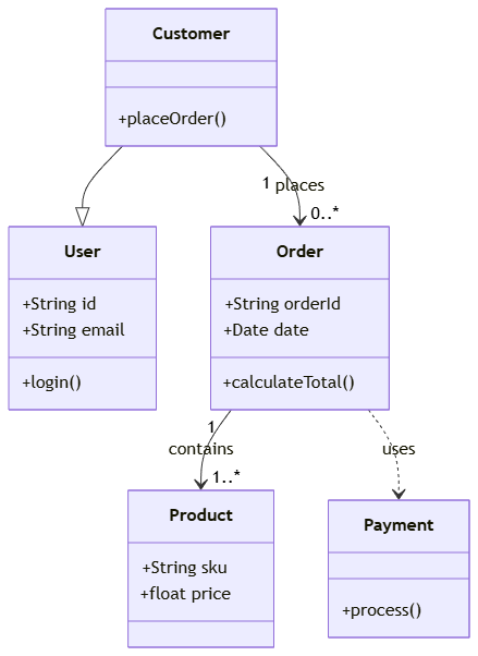
Purpose: The most important diagram — shows the static structure of classes and relationships.
Key Notation:
Class Box: Top = name, Middle = attributes, Bottom = operations (methods).
Visibility: + public, - private, # protected, ~ package.
Relationships:
Association (solid line).
Aggregation (hollow diamond — "has-a" weak).
Composition (filled diamond — "owns" strong, lifecycle dependent).
Generalization (hollow arrow — inheritance).
Dependency (dashed arrow).
Realization (dashed arrow with hollow triangle — implements interface).
Example – E-commerce Domain:
classDiagram
    class User {
        +String id
        +String email
        +login()
    }
    class Customer {
        +placeOrder()
    }
    class Order {
        +String orderId
        +Date date
        +calculateTotal()
    }
    class Product {
        +String sku
        +float price
    }
    class Payment {
        +process()
    }

    Customer --|> User
    Customer "1" --> "0..*" Order : places
    Order "1" --> "1..*" Product : contains
    Order ..> Payment : uses
Advanced: Abstract classes in italics, interfaces with <<interface>>.
Ninja Tip: Apply SOLID principles visibly (e.g., show interfaces for dependency inversion).
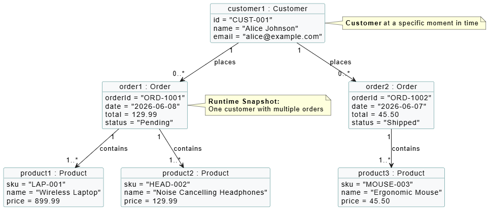
Purpose: Instantiation of a class diagram at a specific moment (runtime view).
When to Use: Debugging complex object graphs or explaining examples.
Example: One Customer with two Order instances linked to Products.
Purpose: Shows how objects interact over time for a specific scenario.
Key Elements:
Lifelines (vertical dashed lines).
Messages (horizontal arrows): synchronous (filled arrow), asynchronous (open), return (dashed).
Activation bars, loops, alternatives (alt), options (opt), parallels (par).
Example – Order Placement:
Customer → OrderController: createOrder()
OrderController → Order: new()
Order → Product: checkStock()
Order → PaymentService: processPayment()
Return success.
Visual Example:
PlantUML Code:
@startuml
' Object Diagram - E-commerce Snapshot (Runtime View)

skinparam shadowing false
skinparam classFontSize 14
skinparam monochrome false
skinparam classAttributeIconSize 0
skinparam objectBackgroundColor #F8F9FA
skinparam objectBorderColor #2C7A7B

' Objects (Instances)
object "customer1 : Customer" as cust {
id = "CUST-001"
name = "Alice Johnson"
email = "[email protected]"
}

object "order1 : Order" as ord1 {
orderId = "ORD-1001"
date = "2026-06-08"
total = 129.99
status = "Pending"
}

object "order2 : Order" as ord2 {
orderId = "ORD-1002"
date = "2026-06-07"
total = 45.50
status = "Shipped"
}

object "product1 : Product" as p1 {
sku = "LAP-001"
name = "Wireless Laptop"
price = 899.99
}

object "product2 : Product" as p2 {
sku = "HEAD-002"
name = "Noise Cancelling Headphones"
price = 129.99
}

object "product3 : Product" as p3 {
sku = "MOUSE-003"
name = "Ergonomic Mouse"
price = 45.50
}

' Relationships
cust "1" --> "0..*" ord1 : places
cust "1" --> "0..*" ord2 : places

ord1 "1" --> "1..*" p1 : contains
ord1 "1" --> "1..*" p2 : contains

ord2 "1" --> "1..*" p3 : contains

' Notes
note right of cust
<b>Customer</b> at a specific moment in time
end note

note right of ord1
<b>Runtime Snapshot:</b>
One customer with multiple orders
end note

@enduml
Ninja Tip: Use for critical or complex flows. Combine with use cases.
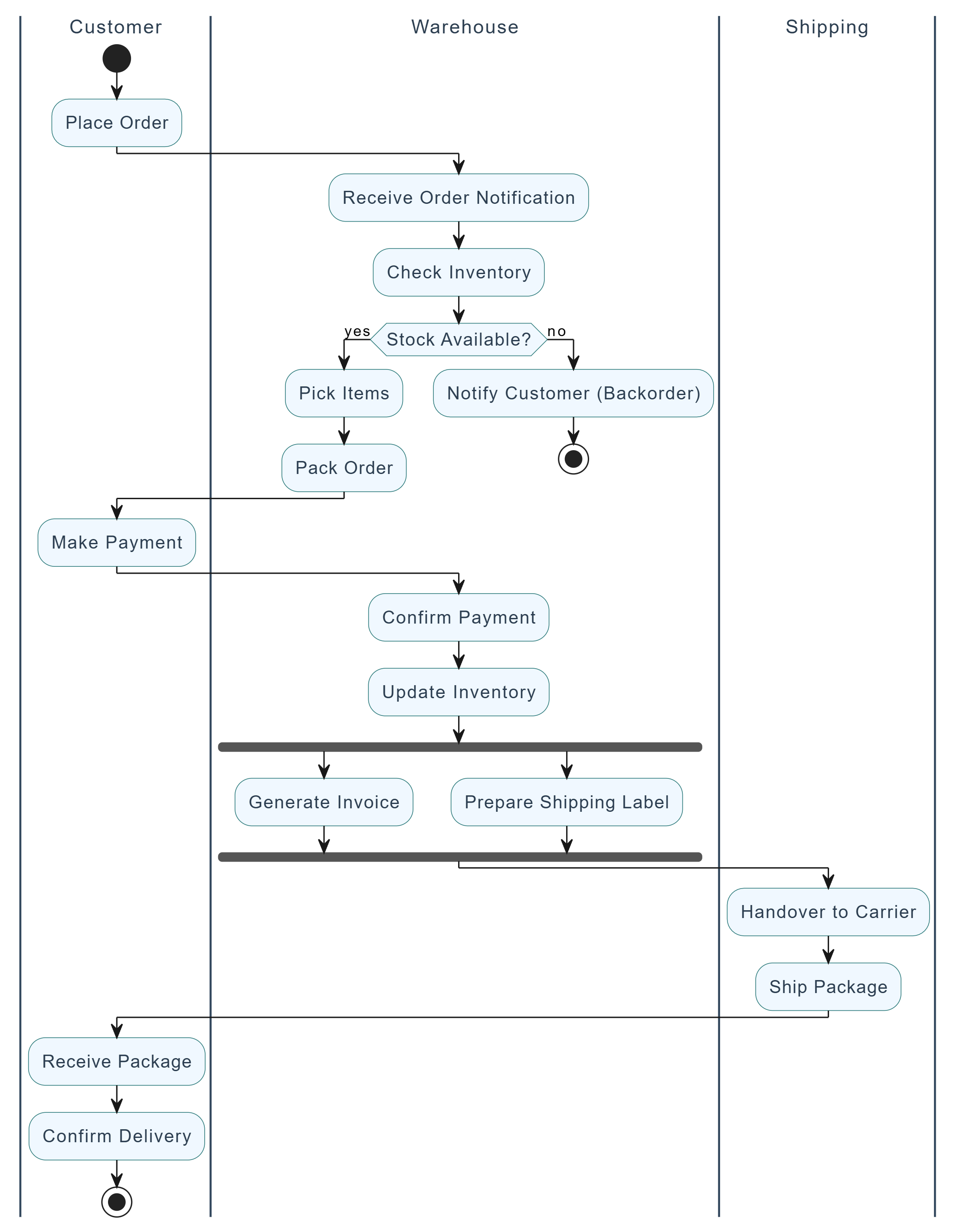
Purpose: Business processes, algorithms, or workflows (like flowcharts on steroids).
Key Elements:
Start/End nodes.
Actions (rounded rectangles).
Decision nodes (diamonds).
Fork/Join (bars for parallelism).
Swimlanes (for responsibilities).
Example: Order Fulfillment process with swimlanes (Customer, Warehouse, Shipping).
@startuml
' Activity Diagram: Order Fulfillment Process with Swimlanes

skinparam shadowing false
skinparam activity {
BackgroundColor #F0F8FF
BorderColor #2C7A7B
FontColor #2C3E50
FontSize 13
}

skinparam swimlane {
BorderColor #34495E
TitleFontColor #2C3E50
TitleFontSize 14
}

|Customer|
start
:Place Order;
|Warehouse|
:Receive Order Notification;
:Check Inventory;

if (Stock Available?) then (yes)
:Pick Items;
:Pack Order;
else (no)
:Notify Customer (Backorder);
stop
endif

|Customer|
:Make Payment;

|Warehouse|
:Confirm Payment;
:Update Inventory;

fork
:Generate Invoice;
fork again
:Prepare Shipping Label;
end fork

|Shipping|
:Handover to Carrier;
:Ship Package;

|Customer|
:Receive Package;
:Confirm Delivery;

stop
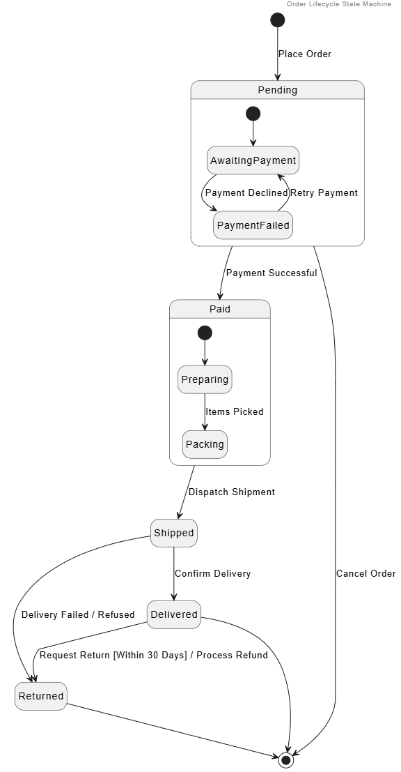
@endumlPurpose: Shows states an object goes through and transitions triggered by events.
Key Elements:
States (rounded rectangles).
Transitions (arrows with event [guard] / action).
Initial/Final states, composite states.
Example – Order states: Pending → Paid → Shipped → Delivered → Returned (with guards like "payment successful").
@startuml
header Order Lifecycle State Machine
hide empty description

[*] --> Pending : Place Order

state Pending {
[*] --> AwaitingPayment
AwaitingPayment --> PaymentFailed : Payment Declined
PaymentFailed --> AwaitingPayment : Retry Payment
}

Pending --> Paid : Payment Successful

state Paid {
[*] --> Preparing
Preparing --> Packing : Items Picked
}

Paid --> Shipped : Dispatch Shipment

Shipped --> Delivered : Confirm Delivery
Shipped --> Returned : Delivery Failed / Refused

Delivered --> Returned : Request Return [Within 30 Days] / Process Refund

Returned --> [*]
Delivered --> [*]
Pending --> [*] : Cancel Order
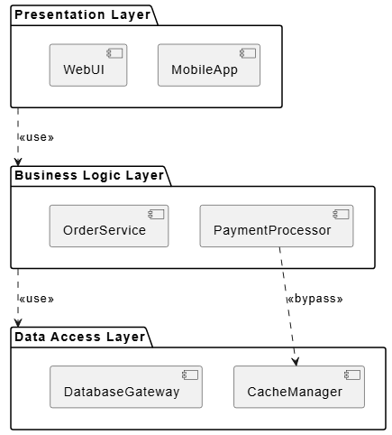
@endumlComponent Diagram: High-level software modules and interfaces (provided/required).
Deployment Diagram: Hardware nodes, artifacts deployed on them (servers, databases, etc.).
Example: Web app with Frontend component → Backend API component → Database. Deployed on AWS EC2 + RDS.
Organize classes into namespaces/packages.
PlantUML Code:
@startuml
skinparam componentStyle uml2

package "Presentation Layer" {
    [MobileApp]
    [WebUI]
}

package "Business Logic Layer" {
    [PaymentProcessor]
    [OrderService]
}

package "Data Access Layer" {
    [CacheManager]
    [DatabaseGateway]
}

"Presentation Layer" ..> "Business Logic Layer" : <<use>>
"Business Logic Layer" ..> "Data Access Layer" : <<use>>
[PaymentProcessor] ..> [CacheManager] : <<bypass>>

@enduml
Similar to sequence but emphasizes relationships (numbered messages).
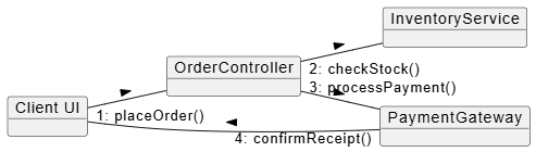
PlantUML Code:
@startuml
left to right direction

object "Client UI" as UI
object "OrderController" as Ctrl
object "InventoryService" as Inv
object "PaymentGateway" as Pay

UI -- Ctrl : "1: placeOrder()" >
Ctrl -- Inv : "2: checkStock()" >
Ctrl -- Pay : "3: processPayment()" >
Pay -- UI : "4: confirmReceipt()" >
@endumlInternal structure of a class/component with ports.
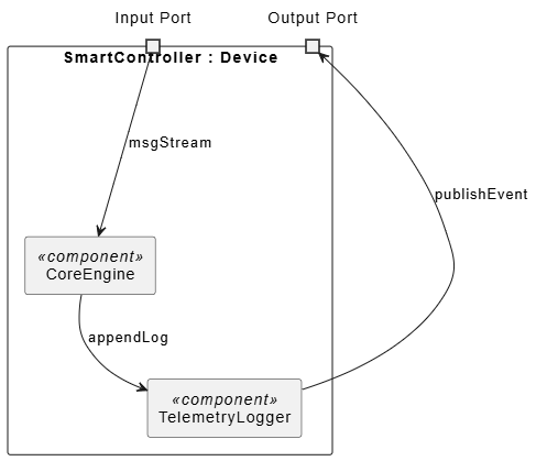
PlantUML Code:
@startuml
skinparam componentStyle uml2

rectangle "SmartController : Device" {
port "Input Port" as input
port "Output Port" as output

rectangle "CoreEngine" as core <<component>>
rectangle "TelemetryLogger" as logger <<component>>

input --> core : msgStream
core --> logger : appendLog
logger --> output : publishEvent
}
@endumlFor complex interactions or real-time constraints.
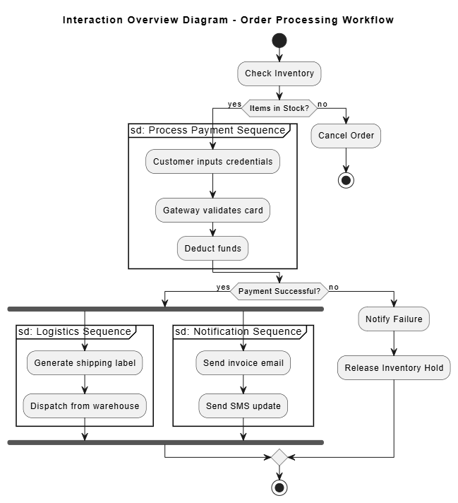
PlantUML Code:
@startuml
skinparam activityShape octagon

title Interaction Overview Diagram - Order Processing Workflow

start

:Check Inventory;

if (Items in Stock?) then (yes)
partition "sd: Process Payment Sequence" {
:Customer inputs credentials;
:Gateway validates card;
:Deduct funds;
}
else (no)
:Cancel Order;
stop
endif

if (Payment Successful?) then (yes)
fork
partition "sd: Logistics Sequence" {
:Generate shipping label;
:Dispatch from warehouse;
}
fork again
partition "sd: Notification Sequence" {
:Send invoice email;
:Send SMS update;
}
end fork
else (no)
:Notify Failure;
:Release Inventory Hold;
endif

stop
@enduml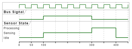
PlantUML Code:
@startuml
clock clk with period 50
binary "Bus Signal" as BUS
robust "Sensor State" as SENSOR

@0
BUS is Low
SENSOR is Idle

@100
BUS is High
SENSOR is Sensing

@300
SENSOR is Processing
BUS is Low

@400
SENSOR is Idle
@endumlStart Simple: 80% of value comes from Use Case + Class + Sequence diagrams.
Consistency: Follow naming conventions (nouns for classes, verbs for methods).
Iteration: Models evolve — use tools with version control (Git for PlantUML/Mermaid).
Tools:
Free: PlantUML, Mermaid.js, Visual Paradigm Online.
Professional:Visual Paradigm Desktop.
Model-Driven Architecture (MDA): Generate code from models (partial success in practice).
Integration with Agile: Use UML for spikes, architecture decision records (ADRs), and sprint planning.
Common Pitfalls: Over-modeling (analysis paralysis), ignoring the audience, outdated diagrams.
Ninja Moves:
Profile UML for domains (e.g., SysML for systems engineering).
Use color, layout, and layering for readability.
Combine with Domain-Driven Design (DDD) bounded contexts in package diagrams.
Generate diagrams from code (reverse engineering) or vice versa.
Mastering UML transforms you from a coder who "just builds things" into a system thinker who designs robust, maintainable, and communicable solutions. Start today by picking one diagram type relevant to your current project — sketch a Use Case or Class diagram by hand or in draw.io. Practice daily, review open-source project diagrams, and gradually incorporate more types.
Learning Roadmap:
Week 1: Use Case + Class diagrams.
Week 2-3: Sequence + Activity.
Ongoing: Apply to real projects, review with peers.
Advanced: Architecture views, SysML, code generation.
UML is a skill that compounds: the better your models, the better your software — and the more valuable you become. Keep your diagrams alive, not shelf-ware.
Recommended Resources:
Official OMG UML Specification (for reference).
Books: "UML Distilled" by Martin Fowler (best starter), "The Unified Modeling Language User Guide" by Booch et al.
Online: PlantUML docs, Visual Paradigm tutorials.
Now go sketch your first diagram — your inner UML Ninja is waiting!
If you'd like me to generate more specific diagram images, expand on any section, or create examples tailored to your domain (e.g., mobile app, microservices, game), just let me know.