A UML use-case diagram is a high-level visual representation of how users (or external systems) interact with your application. It focuses on business value and user goals, not technical implementation.
Think of it as the "glue" that holds your requirements model together. It is always supported by detailed text documents (use-case specifications and actor definitions), but the diagram itself provides an at-a-glance view of system scope and stakeholder interactions.
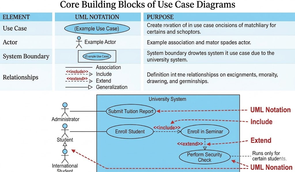
| Element | UML Notation | Purpose |
|---|---|---|
| Use Case | Horizontal ellipse ( ) |
A sequence of actions that delivers measurable value to an actor. |
| Actor | Stick figure 🧍 |
Any person, organization, external system, or timer that interacts with the system. |
| System Boundary | Rectangle ▭ around use cases |
Defines what is inside your system vs. what is outside your control. |
| Relationships | Lines with/without arrows & stereotypes | Show how actors and use cases connect, depend on, or generalize each other. |
💡 Golden Rule: Build use-case models from the project stakeholder's perspective, not the developer's perspective.
| Relationship | Notation | When to Use | Real-World Analogy |
|---|---|---|---|
| Association | Solid line ── |
An actor participates in a use case (supplies info, starts it, or receives output). | A customer walks into a store. |
<<include>> |
Dashed line + open arrow ⇢ |
A use case must be executed at a specific point. Reusable, mandatory logic. | Calling a function: checkout() → calculateTax() |
<<extend>> |
Dashed line + open arrow ⇢ |
A use case might run during certain steps. Optional/conditional logic. | A pop-up coupon or error check that may or may not trigger. |
| Generalization | Solid line + closed arrow ▶ |
"Is a" or "Is like" relationship. The child inherits/rewrites logic from the parent. | International Student is like Student but with extra steps. |
(Synthesized from Guidelines #58–#86)
Start use-case names with a strong verb: Withdraw Funds, Register Student. Avoid weak verbs like Process, Perform, or Do.
Use domain terminology: Stakeholders understand Deliver Shipment better than Convey Package Via Vehicular Transportation.
Name actors with singular, role-based nouns: Use Customer Support, not Junior CSR or Manager. Model roles, not job titles.
Apply the "Is Like" rule for generalization: The sentence "[Child] is like [Parent]" must make logical sense.
Place primary actors top-left: Western readers start here. Critical actors/use cases should anchor the diagram.
Keep actors on the outer edges: Actors are outside your system's scope. Never draw them inside the boundary box.
Stack use cases to imply flow: Place earlier use cases above later ones. (Note: This only implies order; actual sequencing belongs in textual preconditions or activity diagrams.)
Inheritance goes down: Place inheriting actors or use cases below their parents.
Draw <<include>> left-to-right, and <<extend>> top-to-bottom for visual consistency.
Avoid arrowheads on actor-use case lines unless you must show a passive actor or your audience knows UML well. Arrowheads indicate initial invocation, not data flow.
Use <<include>> sparingly and precisely: Only when you know exactly when the sub-use case runs.
Apply <<extend>> sparingly: They easily clutter diagrams. Keep extension conditions/points in your text specifications, not on the diagram.
Never exceed 2 levels of nesting: UseCaseA → includes UseCaseB → includes UseCaseC indicates functional decomposition (a design activity), not requirements modeling.
Never connect actors to each other: Actor-to-actor interactions belong in use-case text, not on the diagram.
Use the boundary box only when it adds value: Great for showing release phases (nested boxes for Phase 1, 2, 3) or system scope. Omit if redundant.
Mark external systems with <<system>>: e.g., Payment Processor <<system>>.
Introduce a Time actor for scheduled events: e.g., Submit Taxes triggered monthly by a clock actor.
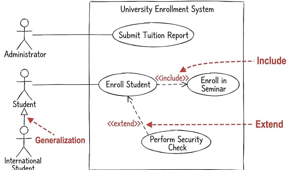
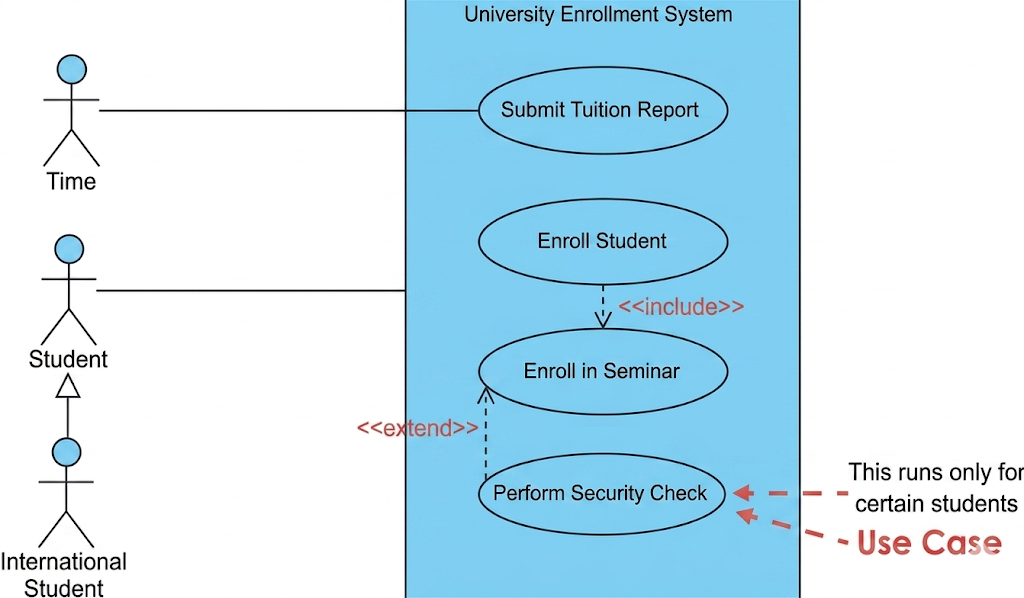
Let's model a simplified enrollment process using the guidelines above.
Student (Primary actor)
International Student (Specialized actor)
Time (Triggers periodic tasks)
Enroll Student
Enroll in Seminar
Perform Security Check
Submit Tuition Report (Monthly)
Student ── Enroll Student
Enroll Student <<include>> Enroll in Seminar (Mandatory step)
Perform Security Check <<extend>> Enroll Student (Runs only for certain students, at unknown steps)
International Student ▶ Student (Is like a student, but with extra requirements)
Time ── Submit Tuition Report
[Time] ────────(Submit Tuition Report)

[Student] ────────(Enroll Student)
                      │
                      │ <<include>>
                      ▼
                  (Enroll in Seminar)

[Perform Security Check]
          │ <<extend>>
          ▼
      (Enroll Student)

      ▲
      │ (Generalization)
[International Student]
(Draw a rectangle around Enroll Student, Enroll in Seminar, and Perform Security Check to mark system scope. Place Time and actors on the outside edges.)
| Mistake | Why It's Wrong | Fix |
|---|---|---|
Using technical names like Process_DB_Transaction |
Stakeholders don't understand implementation details. | Use Withdraw Funds or Generate Report. |
| Drawing arrows showing data flow | UML associations show initiation, not data movement. | Remove arrows unless showing passive actors. |
Overusing <<extend>> |
Makes diagrams messy and hard to read. | Keep optional/conditional logic in textual use-case specs. |
Connecting Customer to Admin directly |
Actors don't interact on use-case diagrams. | Describe their interaction in a use-case scenario. |
Showing >2 levels of <<include>> |
Turns into functional decomposition (design, not requirements). | Flatten the model or move details to sequence/activity diagrams. |
Use-case names start with a strong verb + domain term
Actor names are singular roles, not job titles
Primary actor is top-left; all actors are outside the boundary
<<include>> = mandatory, known step (draw left→right)
<<extend>> = optional, conditional step (draw top→bottom, use sparingly)
Generalization passes the "is like" test
No actor-to-actor lines
Extension points/conditions kept in text, not diagram
Boundary box used only for scope or release phasing
Use-case diagrams are communication tools, not technical blueprints. Follow these style guidelines to keep your models clean, stakeholder-friendly, and focused on business value. Always remember Agile Modeling's core practice: Depict Models Simply. If a detail doesn't help stakeholders understand the system's purpose, leave it out of the diagram and document it elsewhere.
For deeper dives into usage scenarios, refer to textual use-case specifications and complementary UML artifacts like Activity Diagrams (for flow) and Sequence Diagrams (for detailed interactions).