
If you've started learning software architecture, systems design, or enterprise modeling in the last few years, you've probably encountered two dominant trends:
Diagram-as-Code (DaC): Tools like PlantUML, Mermaid, Structurizr, and D2 that let you write diagrams as plain text.
AI-Generated Diagrams: Large language models (LLMs) that can produce diagrams from natural language prompts.
Both of these approaches are exciting. They're fast, they integrate with version control, and they lower the barrier to creating architecture visuals. If you search online today, you'll find countless blog posts proclaiming that traditional modeling tools are dead.
They're not.
While Diagram-as-Code and AI offer undeniable speed and convenience, they leave critical gaps when it comes to enterprise-grade architecture work: standards compliance (TOGAF, UML, BPMN, ArchiMate), deep model validation, bidirectional code and database synchronization, living models that evolve with your system, and professional team collaboration workflows.
This tutorial is written for beginners who want to understand:
What Diagram-as-Code and AI can and cannot do for you
Why a professional modeling tool like Visual Paradigm remains essential
How to combine these approaches for maximum productivity without sacrificing quality or rigor
By the end of this guide, you'll have a clear mental model of when to reach for a text-based diagram, when to fire up Visual Paradigm, and how to build a sustainable architecture practice that scales with your team.
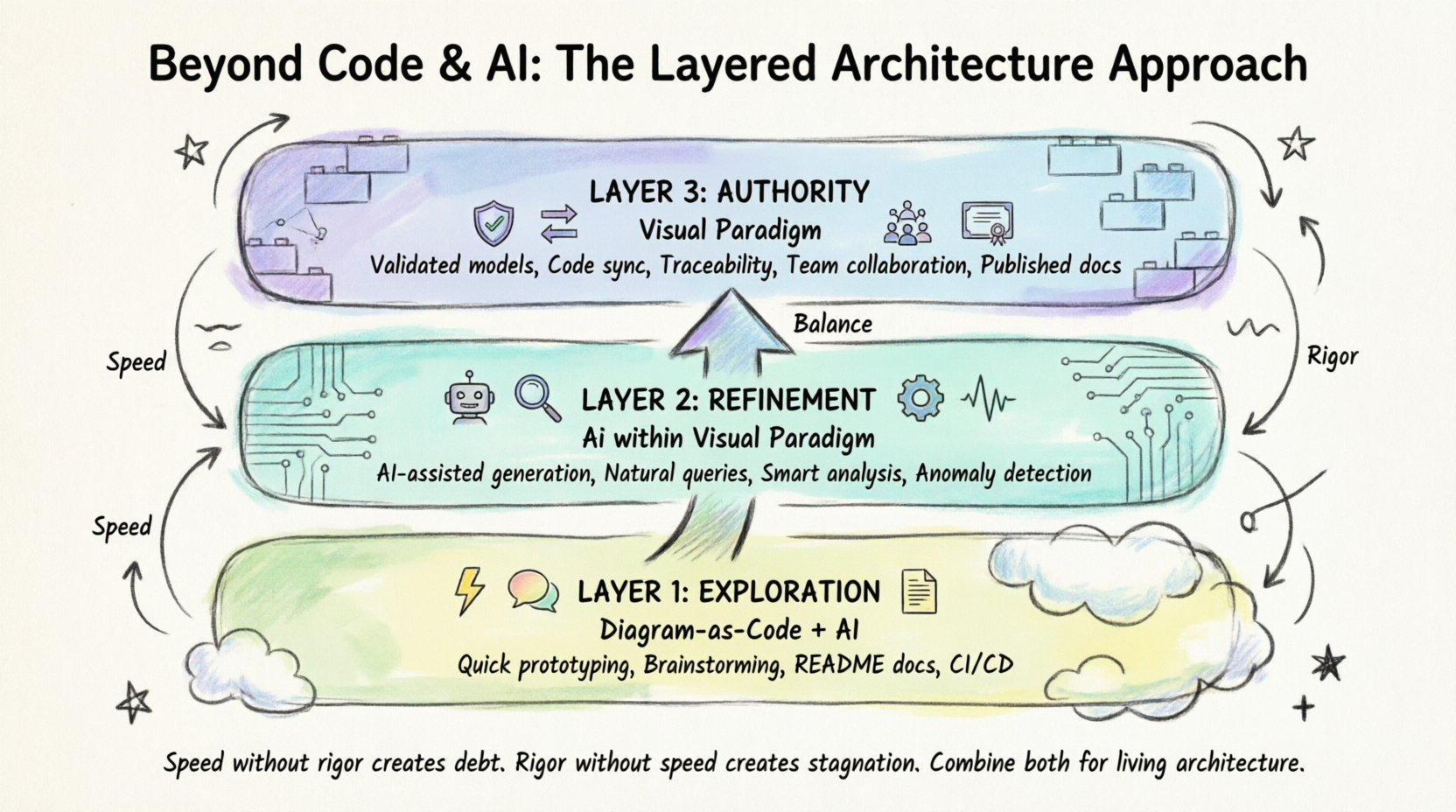
Diagram-as-Code (DaC) is the practice of defining diagrams using plain text or code rather than dragging and dropping shapes on a canvas. You write a description of your system, and a tool renders it visually.
Popular DaC tools include:
| Tool | Strengths | Best For |
|---|---|---|
| PlantUML | Huge ecosystem, many diagram types, mature | Sequence, class, component diagrams |
| Mermaid | Native GitHub/GitLab rendering, simple syntax | Quick diagrams in Markdown docs |
| Structurizr | C4 model focus, workspace concept | Software architecture (C4) |
| D2 | Modern syntax, theming, animations | Developer-friendly architecture diagrams |
| Graphviz (DOT) | Graph theory, auto-layout | Dependency graphs, network topology |
This refers to using LLMs (like ChatGPT, Claude, or built-in AI assistants) to:
Generate PlantUML/Mermaid code from a natural language description
Explain or critique an existing diagram
Convert one diagram format to another
Suggest architectural improvements
Version Control Friendly: Text files work perfectly with Git (diffs, merges, branches).
Speed: You can produce a diagram in seconds.
Automation: Diagrams can be generated in CI/CD pipelines.
Low Barrier: No expensive licenses, no complex tool installation.
Developer Comfort: Developers prefer writing code over dragging shapes.
All of this is genuinely valuable. But it's only part of the picture.
Before we discuss limitations, let's give DaC its due credit.
Because DaC diagrams are plain text, they integrate seamlessly with Git. You get:
Diff and merge: See exactly what changed between commits
Branching: Experiment with architectural changes in feature branches
Review: Use pull requests to review diagram changes
The same input always produces (roughly) the same output. This makes diagrams reproducible and shareable.
You can render diagrams automatically during builds, keeping documentation up to date.
Developers are more likely to maintain diagrams if they can write them in a text editor alongside their code.
Now let's examine the critical gaps that appear when you rely only on DaC and AI for your architecture work.
The Problem: DaC tools produce images or rendered SVGs. They don't maintain a rich, queryable model behind the diagram.
When you write a PlantUML class diagram, you're describing the appearance of classes and relationships. The tool doesn't understand that:
A "class" is a UML construct with specific rules about inheritance, multiplicity, and visibility
A relationship labeled <<uses>> should conform to dependency semantics
Changing a class name in one diagram should update it everywhere it appears
Why it matters: Without a semantic model, you can't:
Query your architecture ("Show me all services that depend on the Payment Gateway")
Validate consistency across diagrams
Perform impact analysis when something changes
The Problem: DaC tools don't enforce modeling standards. You can draw a PlantUML diagram that looks like a UML sequence diagram but violates UML rules (e.g., incorrect message types, illegal lifeline interactions, missing combined fragments).
Why it matters: In regulated industries (finance, healthcare, defense), architecture artifacts may need to comply with:
UML 2.5.1 (Unified Modeling Language)
BPMN 2.0 (Business Process Model and Notation)
TOGAF ADM (The Open Group Architecture Framework)
ArchiMate 3.2 (Enterprise Architecture Language)
SysML (Systems Modeling Language)
DaC tools simply don't validate against these standards.
The Problem: DaC tools use automatic layout engines. This means:
You have minimal control over where elements appear
Complex diagrams often become unreadable
Small text changes can completely rearrange the layout
Branding, custom shapes, and polished visuals are difficult or impossible
Why it matters: When presenting architecture to stakeholders, executives, or clients, you need polished, presentation-ready diagrams. Auto-layout often produces diagrams that look "generated" and unprofessional.
The Problem: DaC diagrams are one-way artifacts. You write text → you get an image. There's no mechanism to:
Generate working code from your diagrams
Reverse-engineer existing code into diagrams
Keep diagrams synchronized with your actual codebase or database schema
Why it matters: This creates documentation drift. The diagram you created in Sprint 3 no longer reflects the code in Sprint 12. Without synchronization, diagrams become misleading.
The Problem: DaC files are text files. While this is great for Git, it's terrible for:
Non-technical stakeholders who need to review and comment on diagrams
Simultaneous editing by multiple team members
Structured review and approval workflows
Traceability (linking requirements → design → implementation → test)
Why it matters: Enterprise architecture is a team sport. Product owners, business analysts, QA engineers, and architects all need to collaborate on models—not just developers.
The Problem: When you ask an LLM to generate a diagram, it:
May invent components that don't exist in your system
Doesn't understand your existing architecture unless you provide full context
Cannot guarantee the output conforms to any standard
Produces a "one-off" artifact with no connection to your model repository
Why it matters: AI-generated diagrams are great for brainstorming and prototyping but dangerous if treated as authoritative architecture documentation.
Visual Paradigm (VP) is a professional modeling platform that addresses every one of the gaps above. Let's examine how.
Unlike DaC tools that produce flat images, Visual Paradigm maintains a centralized model repository. Every element you create (a class, a component, a business process, a requirement) is a model element with:
A unique identity
Properties, stereotypes, and tagged values
Relationships to other elements
Appearances in multiple diagrams
Example: If you create a PaymentService component in a Component Diagram and then reuse it in a Deployment Diagram, VP understands these are the same element. Renaming it in one place updates it everywhere.
VP natively supports and validates:
UML 2.5.1 (all 14 diagram types)
BPMN 2.0 (with execution semantics)
TOGAF ADM (full Architecture Development Method support)
ArchiMate 3.2
SysML v1.x and v2
ERD (Entity-Relationship Diagrams)
DMN (Decision Model and Notation)
CMMN (Case Management Model and Notation)
It will warn you when you violate rules (e.g., "A Generalization relationship cannot connect a Class to an Actor").
VP provides:
Drag-and-drop canvas with precise control
Custom shapes, colors, and themes
Alignment tools, grids, and snapping
Presentation mode for stakeholder reviews
Export to high-resolution PNG, SVG, PDF, and more
| Feature | What It Does |
|---|---|
| Forward Engineering | Generate Java, C#, Python, C++, SQL DDL, and more from your models |
| Reverse Engineering | Import existing source code or database schemas into models |
| Round-Trip Engineering | Keep code and models synchronized bidirectionally |
| ORM Mapping | Map object models to relational database schemas |
Because VP maintains a model repository:
Changes propagate across all diagrams automatically
You can perform impact analysis ("What breaks if we change this interface?")
Traceability matrices link requirements to design to code to tests
Models can be published as interactive web documentation
Gap Analysis: Compare As-Is and To-Be architectures
Impact Analysis: Understand the ripple effects of changes
Metrics: Calculate coupling, cohesion, complexity
Simulation: Simulate BPMN processes for performance bottlenecks
EA Grid: Cross-reference architecture viewpoints
Teamwork Server: Central model repository with check-in/check-out
Review and Comment: Stakeholders can annotate diagrams
Baseline and Versioning: Track model evolution over time
Access Control: Role-based permissions for different team members
Let's look at concrete examples that illustrate the difference between DaC and a professional tool like Visual Paradigm.
Suppose you're architecting an e-commerce system. Here's a PlantUML component diagram:
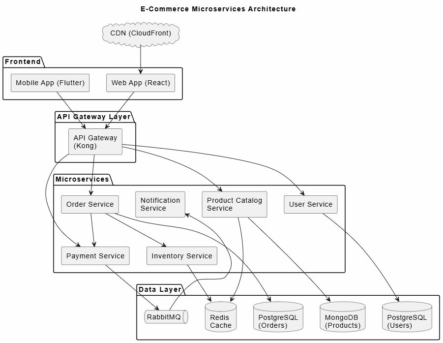
@startuml
title E-Commerce Microservices Architecture

skinparam componentStyle rectangle
skinparam backgroundColor #FEFEFE

cloud "CDN (CloudFront)" as cdn

package "Frontend" {
  [Web App (React)] as web
  [Mobile App (Flutter)] as mobile
}

package "API Gateway Layer" {
  [API Gateway\n(Kong)] as gateway
}

package "Microservices" {
  [User Service] as user
  [Product Catalog\nService] as catalog
  [Order Service] as order
  [Payment Service] as payment
  [Inventory Service] as inventory
  [Notification\nService] as notification
}

package "Data Layer" {
  database "PostgreSQL\n(Users)" as db_users
  database "MongoDB\n(Products)" as db_products
  database "PostgreSQL\n(Orders)" as db_orders
  queue "RabbitMQ" as mq
  database "Redis\nCache" as cache
}

web --> gateway
mobile --> gateway
cdn --> web

gateway --> user
gateway --> catalog
gateway --> order
gateway --> payment

user --> db_users
catalog --> db_products
catalog --> cache
order --> db_orders
order --> payment
order --> inventory
payment --> mq
mq --> notification
inventory --> cache

@enduml
What this gets right:
Quick to write and modify
Can be version-controlled in Git
Renders automatically in many platforms
What this misses:
❌ No semantic model—Order Service here is just text in a box, not a model element with defined interfaces, ports, or dependencies
❌ No validation—nothing prevents you from drawing an arrow from a database to a CDN that makes no architectural sense
❌ No reuse—if you want a Deployment Diagram showing where these services run, you must retype everything
❌ No traceability—you can't link these components to business requirements or user stories
❌ No code generation—you can't generate Spring Boot project skeletons from this
In Visual Paradigm, you would create the same architecture, but with these additional capabilities:
When you create Order Service as a component in VP, it becomes a first-class model element. You can:
Add provided/required interfaces with defined operations
Specify ports and connectors with proper UML semantics
Reuse the exact same Order Service element in:
A Sequence Diagram showing order flow
A Deployment Diagram showing it running on Kubernetes
A Data Flow Diagram showing how data moves through it
If you change the Payment Service interface (e.g., add a new refundPayment() operation), VP can show you:
Every diagram where Payment Service appears
Every component that depends on it
Every requirement traced to it
Every test case linked to it
From the component model, VP can generate:
// Auto-generated from Visual Paradigm Component Model
package com.ecommerce.order;

/**
 * Order Service Component
 *
 * Model Element ID: VP-COMP-2026-00142
 * Traced to Requirement: REQ-ORDER-001, REQ-ORDER-002
 */
public interface OrderService {

    /**
     * Create a new order
     * @param orderRequest The order details
     * @return OrderConfirmation with order ID
     */
    OrderConfirmation createOrder(OrderRequest orderRequest);

    /**
     * Retrieve order by ID
     * @param orderId Unique order identifier
     * @return Order details
     */
    Order getOrder(String orderId);

    /**
     * Cancel an existing order
     * @param orderId Unique order identifier
     * @return Cancellation status
     */
    CancellationStatus cancelOrder(String orderId);
}
Here's a PlantUML activity diagram for an order fulfillment process:
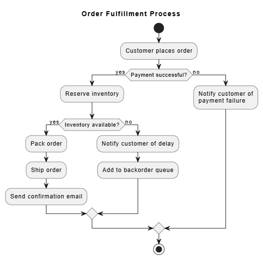
@startuml
title Order Fulfillment Process

start

:Customer places order;

if (Payment successful?) then (yes)
  :Reserve inventory;
  if (Inventory available?) then (yes)
    :Pack order;
    :Ship order;
    :Send confirmation email;
  else (no)
    :Notify customer of delay;
    :Add to backorder queue;
  endif
else (no)
  :Notify customer of\npayment failure;
endif

stop

@enduml
The problem: This is an activity diagram, but real business processes should use BPMN 2.0 because:
BPMN has execution semantics (it can drive workflow engines like Camunda)
BPMN distinguishes between tasks, events, gateways, and pools with precise rules
Auditors and regulators understand BPMN
In Visual Paradigm, the same process would be modeled in BPMN 2.0, and the tool would:
✅ Validate that every process has a Start Event and End Event
✅ Ensure XOR gateways have properly labeled outgoing flows
✅ Check that message flows between pools follow BPMN rules
✅ Allow simulation to find bottlenecks
✅ Export to BPMN XML for execution in a process engine
Suppose you ask an AI to generate a PlantUML sequence diagram for a user login flow:
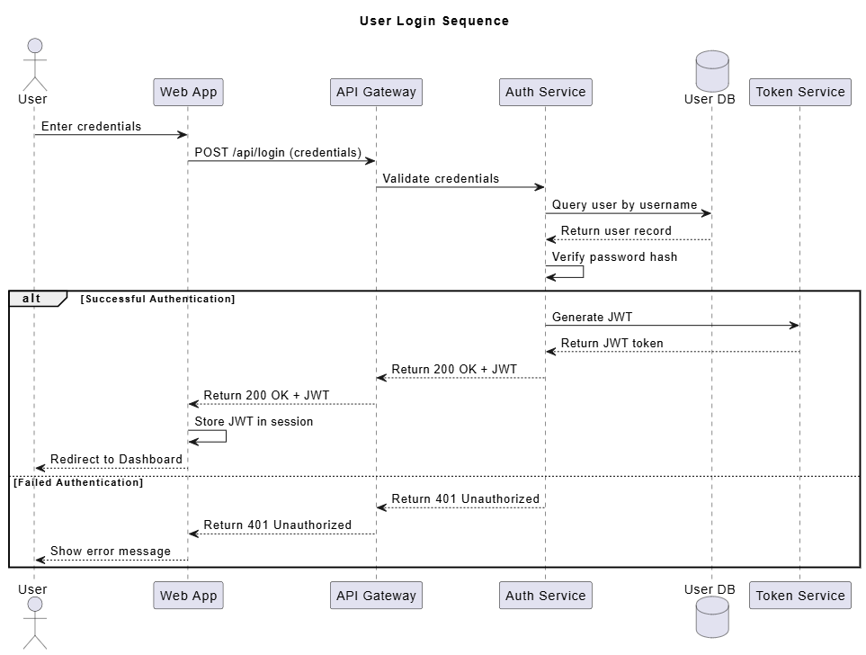
@startuml
title User Login Sequence

actor User
participant "Web App" as Web
participant "API Gateway" as GW
participant "Auth Service" as Auth
database "User DB" as DB
participant "Token Service" as Token

User -> Web: Enter credentials
Web -> GW: POST /api/login (credentials)
GW -> Auth: Validate credentials
Auth -> DB: Query user by username
DB --> Auth: Return user record
Auth -> Auth: Verify password hash

alt Successful Authentication
    Auth -> Token: Generate JWT
    Token --> Auth: Return JWT token
    Auth --> GW: Return 200 OK + JWT
    GW --> Web: Return 200 OK + JWT
    Web -> Web: Store JWT in session
    Web --> User: Redirect to Dashboard
else Failed Authentication
    Auth --> GW: Return 401 Unauthorized
    GW --> Web: Return 401 Unauthorized
    Web --> User: Show error message
end

@enduml
This is a great starting point. But here's what Visual Paradigm adds:
Model Consistency: The Auth Service, User DB, and Token Service lifelines are linked to the actual component model elements. If you rename Auth Service to Identity Service in the component diagram, it updates here too.
Validation: VP checks that:
Return messages match request messages
Lifelines correspond to actual components in your model
Alt fragments have proper guards
Code Generation: From this sequence diagram, VP can generate skeleton controller code:
# Auto-generated from VP Sequence Diagram
# Diagram: User Login Sequence
# Generated: 2026-06-25

from flask import Flask, request, jsonify
import jwt
from datetime import datetime, timedelta

class LoginController:
    """
    Handles user authentication flow.
    Traced to: SEQ-LOGIN-001
    """

    def __init__(self, auth_service, token_service):
        self.auth_service = auth_service
        self.token_service = token_service

    def post_api_login(self, request_data):
        """POST /api/login"""
        credentials = request_data

        # Step 1: Validate credentials via Auth Service
        user = self.auth_service.validate_credentials(credentials)

        if user:
            # Step 2: Generate JWT via Token Service
            token = self.token_service.generate_jwt(user)
            return {"status": 200, "token": token}
        else:
            return {"status": 401, "message": "Unauthorized"}
Visual Paradigm has integrated AI capabilities that complement (rather than replace) its professional modeling features. Here's how they work together:
Instead of asking a generic LLM for a diagram and hoping it's correct, VP's AI:
Generates models within VP's semantic framework
Produces elements that are properly typed (Class, Interface, Component, etc.)
Creates relationships that follow UML/BPMN rules
Places generated elements in your model repository for reuse
You can describe a process in plain English, and VP's AI will:
Parse your description
Generate a properly structured BPMN or UML diagram
Validate it against the relevant standard
Place it in your project's model repository
Example prompt within VP:
"Create a sequence diagram for a hotel booking system where a customer searches for rooms, selects one, provides payment details, and receives a confirmation."
VP generates a model-backed sequence diagram where every lifeline is a real component in your system model.
Natural Language Queries: "Which services have the highest coupling?" or "Show me all requirements not traced to any component."
Anomaly Detection: AI identifies potential issues like circular dependencies, orphaned components, or missing error handling paths.
Documentation Generation: AI generates narrative descriptions of your diagrams for stakeholder documentation.
| Aspect | Standalone AI (e.g., ChatGPT) | AI within Visual Paradigm |
|---|---|---|
| Output format | Text (PlantUML/Mermaid code) | Model elements in repository |
| Validation | None | Standards-compliant validation |
| Consistency | Each generation is independent | Connected to existing model |
| Reuse | Copy-paste text | Model element reuse across diagrams |
| Traceability | None | Full requirement-to-code traceability |
| Evolution | Manual updates | Synchronized model updates |
You don't have to choose between DaC, AI, and Visual Paradigm. The most effective architecture teams use all three strategically.
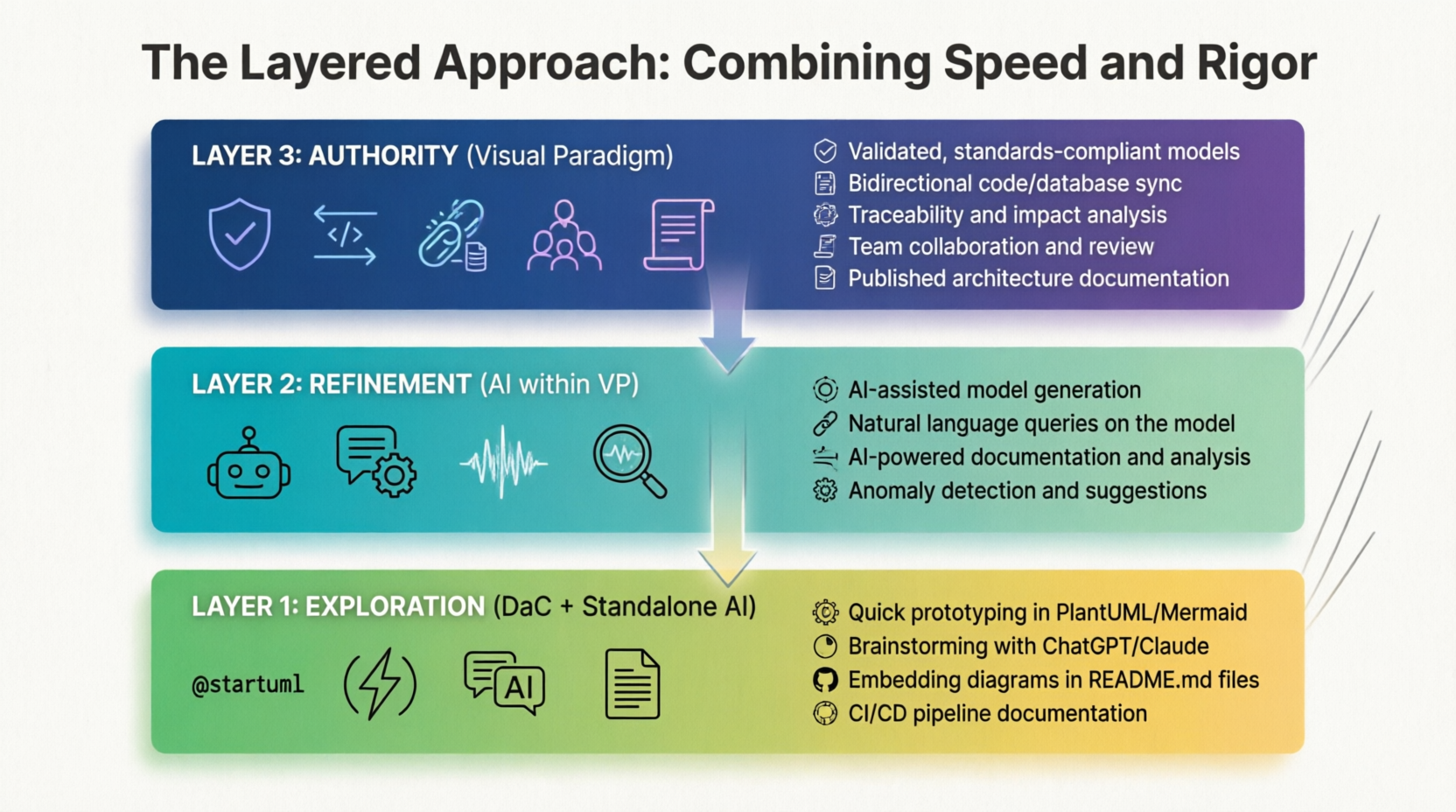
Step 1: Explore with DaC + AI
Use PlantUML or Mermaid to quickly sketch ideas
Use ChatGPT/Claude to brainstorm architectural options
Embed quick diagrams in pull requests and RFCs
Step 2: Formalize in Visual Paradigm
Import or recreate validated designs in VP
Link model elements to requirements
Set up proper UML/BPMN/ArchiMate structures
Step 3: Generate and Synchronize
Use VP's forward engineering to generate code skeletons
Use reverse engineering to import existing code
Enable round-trip engineering for ongoing sync
Step 4: Collaborate and Review
Publish models to VP's Teamwork Server
Use review workflows for stakeholder approval
Generate web-based architecture documentation
Step 5: Maintain as Living Models
Regularly sync code and models
Run impact analysis before making changes
Use VP's AI to detect architectural drift
| Edition | Best For | Key Features |
|---|---|---|
| Community (Free) | Students, personal learning | Basic UML, ERD, limited features |
| Standard | Small teams, individual professionals | All diagram types, code engineering |
| Professional | Growing teams | Teamwork, BPMN simulation, TOGAF |
| Enterprise | Large organizations | Full EA suite, advanced analysis, SSO |
Day 1-2: Learn the Interface
Download and install Visual Paradigm
Complete the built-in tutorial projects
Explore the project browser and model repository
Day 3-4: Create Your First Model
Create a simple Class Diagram for a domain you understand (e.g., a Library system)
Create a Use Case Diagram for the same system
Notice how elements are shared across diagrams
Day 5-7: Try Code Engineering
Forward-engineer Java code from your Class Diagram
Reverse-engineer an existing open-source project
See how the model and code relate
Model a real project you're working on
Experiment with BPMN for business processes
Try the AI assistant for generating initial diagrams
Set up Teamwork Server if you have a team
Explore TOGAF or ArchiMate if you're doing enterprise architecture
Start small. Don't try to model your entire system at once. Begin with one bounded context or one core process.
Use templates. VP comes with templates for common patterns (microservices, layered architecture, SOA). Start from these.
Name things carefully. Model element names should match your codebase. If your Java class is OrderService, name the component OrderService in VP.
Leverage the model repository. Don't just draw diagrams—build a model. Every element should be a reusable model element, not a one-off shape.
Validate early and often. Use VP's validation features to catch modeling errors before they become architectural mistakes.
The narrative that Diagram-as-Code and AI have made professional modeling tools obsolete is a seductive but incomplete story. Here's the reality:
Diagram-as-Code is your sketchpad. It's fast, version-control friendly, and perfect for exploration, quick communication, and developer-facing documentation. Every team should use it.
AI is your brainstorming partner. It can generate ideas, explain patterns, and accelerate initial design. But it lacks the persistent memory, semantic understanding, and validation rigor needed for authoritative architecture.
Visual Paradigm is your system of record. It's where sketches become validated models, where models stay synchronized with code, where stakeholders collaborate with rigor, and where architecture decisions are traced from requirements through implementation to testing.
For beginners entering the world of software architecture, the key insight is this:
Speed without rigor creates technical debt in your architecture documentation. Rigor without speed creates documentation that no one maintains. The winning strategy combines both.
Use PlantUML and AI to move fast. Use Visual Paradigm to move correctly. And use them together to build architectures that are not only well-documented but alive—models that evolve with your system, that your entire team can trust, and that stand up to the scrutiny of audits, reviews, and the relentless pace of change.
Your architecture deserves more than a text file. It deserves a living model.

