
Imagine trying to build a skyscraper using only verbal instructions. The architects, engineers, and construction workers would inevitably end up with a chaotic, structurally unsound mess. Software development is no different. When teams rely solely on text-based requirements or raw code to communicate complex system architectures, misunderstandings are guaranteed.
Enter the Unified Modeling Language (UML). Far from being an outdated relic of the 1990s, UML remains the universal visual language of software engineering. It allows teams to visualize the design of a system, communicate complex logic, and align stakeholders before a single line of code is written. This comprehensive guide will walk beginners through the essentials of UML, proving why it is an indispensable skill for every modern software team.
UML stands for Unified Modeling Language. It is a standardized, general-purpose modeling language created by the Object Management Group (OMG). It provides a set of graphical notation techniques to create visual models of software-intensive systems.
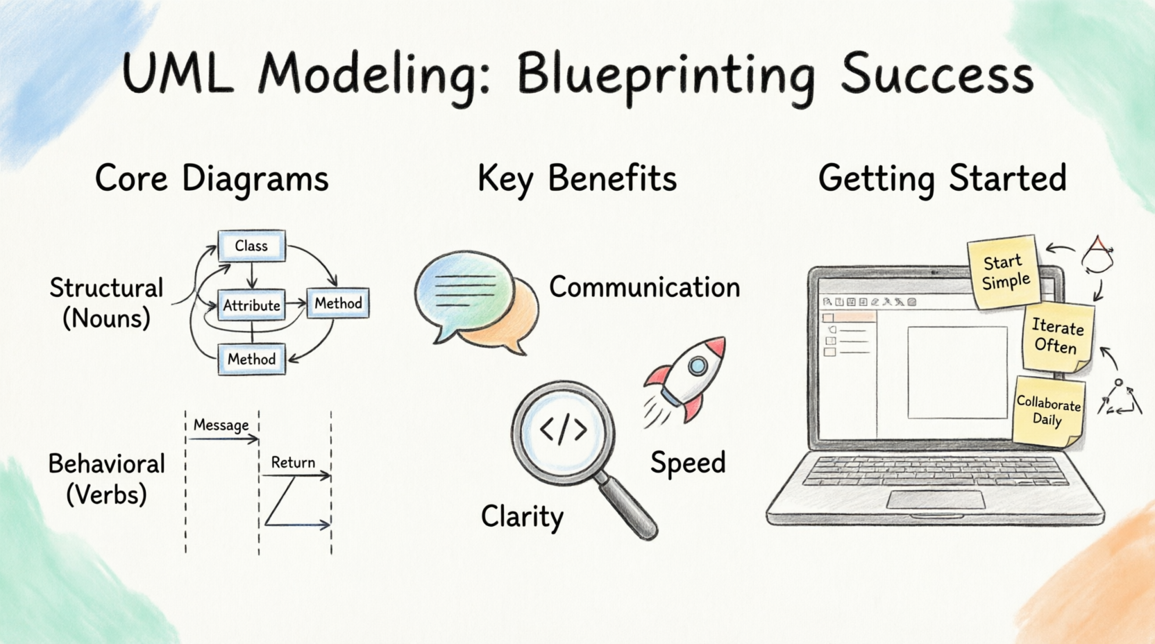
In the era of Agile and DevOps, some mistakenly believe UML is too rigid or "heavy." However, its role has simply evolved. Today, UML is not about creating exhaustive, 500-page documentation that no one reads. Instead, it is used as a communication and design tool.
Modern teams use UML to:
Sketch ideas on a digital whiteboard during sprint planning.
Validate architecture before committing to a complex microservices setup.
Onboard new developers by providing a visual map of the codebase.
UML diagrams are broadly categorized into two main types: Structural (the static parts of the system) and Behavioral (the dynamic, changing parts).
These diagrams show the static structure of the system, its classes, objects, and how they relate to one another.
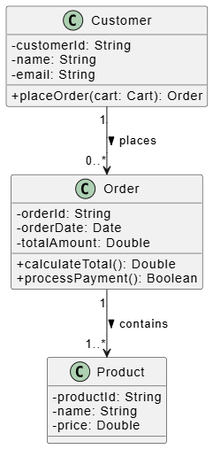
The most popular UML diagram. It shows the system's classes, their attributes, methods, and the relationships (inheritance, association, dependency) between them.
PlantUML Example: E-commerce Order System
@startuml
skinparam classAttributeIconSize 0

class Customer {
  - customerId: String
  - name: String
  - email: String
  + placeOrder(cart: Cart): Order
}

class Order {
  - orderId: String
  - orderDate: Date
  - totalAmount: Double
  + calculateTotal(): Double
  + processPayment(): Boolean
}

class Product {
  - productId: String
  - name: String
  - price: Double
}

Customer "1" --> "0..*" Order : places >
Order "1" --> "1..*" Product : contains >
@enduml
Component Diagram: Shows how larger software components (like APIs or databases) are wired together.
Deployment Diagram: Maps the software components to the physical or cloud hardware (servers, containers) they run on.
These diagrams illustrate how the system behaves, how objects interact, and how the system responds to internal or external stimuli.
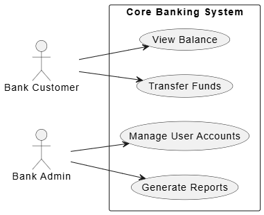
Provides a high-level view of who uses the system and what they can do. It captures functional requirements from the user's perspective.
PlantUML Example: Banking App
@startuml
left to right direction
skinparam packageStyle rectangle

actor "Bank Customer" as customer
actor "Bank Admin" as admin

rectangle "Core Banking System" {
  usecase "View Balance" as UC1
  usecase "Transfer Funds" as UC2
  usecase "Manage User Accounts" as UC3
  usecase "Generate Reports" as UC4
}

customer --> UC1
customer --> UC2
admin --> UC3
admin --> UC4
@enduml
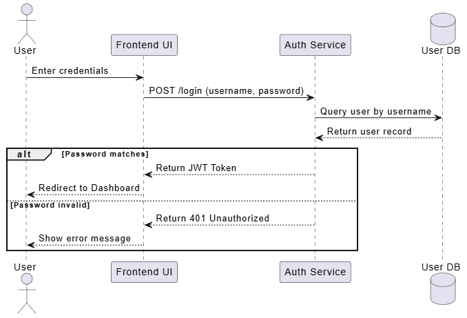
Shows how objects interact in a specific scenario, arranged in time sequence. It is incredibly useful for detailing API calls and complex logic flows.
PlantUML Example: User Login Flow
@startuml
actor User
participant "Frontend UI" as UI
participant "Auth Service" as Auth
database "User DB" as DB

User -> UI: Enter credentials
UI -> Auth: POST /login (username, password)
Auth -> DB: Query user by username
DB --> Auth: Return user record

alt Password matches
    Auth --> UI: Return JWT Token
    UI --> User: Redirect to Dashboard
else Password invalid
    Auth --> UI: Return 401 Unauthorized
    UI --> User: Show error message
end
@enduml
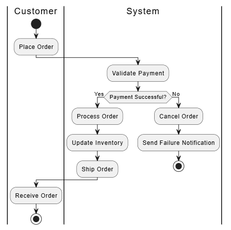
Activity Diagram: Similar to a flowchart, showing the workflow or business process step-by-step.
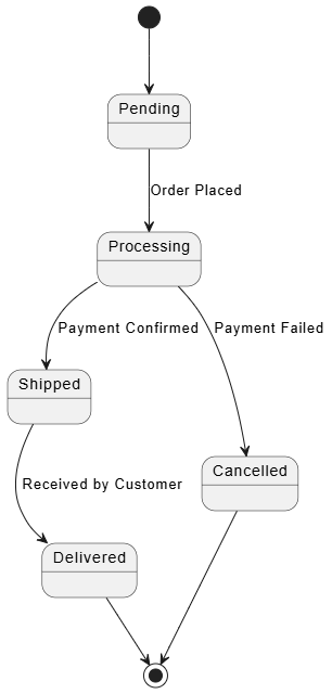
State Machine Diagram: Shows the different states an object can be in (e.g., an Order going from Pending -> Shipped -> Delivered).
Why should a team invest time in drawing diagrams when they could just be coding?
Improved Communication: Code is for machines; UML is for humans. It bridges the gap between technical developers, non-technical product managers, and QA testers. Everyone can understand a Sequence diagram, even if they can't read Java or Python.
Reduced Ambiguity: Text requirements are notoriously open to interpretation. "The system should process the payment quickly" is vague. A Sequence diagram explicitly defines the exact API calls, database queries, and expected responses, leaving no room for guesswork.
Faster Development (Measure Twice, Cut Once): Fixing a design flaw in a UML diagram takes 5 minutes. Fixing that same flaw after the code is written and deployed can take 5 days. UML helps catch architectural bottlenecks and logic errors early in the Software Development Life Cycle (SDLC).
Case Study 1: Microservices API Integration (ROI: 30% reduction in integration bugs)
A fintech startup was struggling with microservices failing to communicate. By mandating Sequence Diagrams for every new API endpoint before coding began, the frontend and backend teams aligned on exact payload structures and error handling. This eliminated "it works on my machine" issues and drastically reduced QA bug reports.
Case Study 2: Legacy System Migration (ROI: Saved 4 weeks of development time)
A healthcare company needed to migrate a monolithic app to the cloud. Developers used Class and Component diagrams to map out hidden dependencies in the legacy code. This visual mapping prevented them from accidentally breaking tightly coupled modules during the migration, saving weeks of debugging.
Pitfall 1: "UML for the sake of UML" (Over-documentation). Creating massive, highly detailed diagrams for every minor feature. Fix: Only diagram complex logic, core architecture, or areas where team alignment is poor.
Pitfall 2: Treating UML as a rigid contract. Spending days perfecting a diagram only to have the code diverge from it immediately. Fix: Treat UML as a living sketch. Update it when the code changes, or use tools that generate UML from code.
Pitfall 3: Ignoring team preferences. Forcing a team to use UML when a quick whiteboard sketch solves the problem. Fix: Use UML when complexity demands it; use sketches for quick huddles.
Start Small: Don't try to model the entire system at once. Start with a high-level Use Case diagram, then drill down into Class diagrams for the core domain, and use Sequence diagrams for complex workflows.
Adopt "Agile Modeling": Keep diagrams lightweight. Use them to facilitate conversation, not to replace it.
Review Together: Use UML diagrams as the centerpiece of your design review meetings. Let the team critique the visual model before writing code.
While there are many tools available (like Lucidchart, Draw.io, or StarUML), Visual Paradigm is highly recommended for teams looking for a robust, professional-grade UML solution.
Why Visual Paradigm?
Comprehensive UML Support: It supports all 14 types of UML diagrams natively, ensuring you never outgrow the tool.
Code Engineering: It features powerful code generation (turning your Class diagrams into Java, C#, Python, etc.) and reverse engineering (generating UML diagrams from existing code). This solves the "outdated documentation" pitfall.
Collaboration: It offers cloud-based collaboration, allowing distributed teams to work on the same models in real-time.
Agile & Project Management Integration: It integrates UML modeling directly with Agile tools, allowing you to link diagrams directly to user stories and tasks.
PlantUML Integration: For developers who prefer "diagrams as code," Visual Paradigm supports PlantUML, allowing you to write scripts and instantly render them into beautiful, standardized UML diagrams within the GUI.
Mastering UML is not about memorizing every obscure arrow type or spending hours drawing perfect boxes. It is about cultivating a mindset of visual thinking and structured communication.
For modern software teams, UML acts as the bridge between abstract ideas and concrete code. By leveraging core diagrams like Class, Use Case, and Sequence diagrams, teams can eliminate ambiguity, catch errors early, and build robust architectures. Whether you are sketching a quick flow on a whiteboard or designing a complex microservices ecosystem in Visual Paradigm, UML empowers you to blueprint your success before you ever write a line of code. Start small, focus on communication, and watch your team's efficiency and code quality soar.

