
In software engineering and systems design, one of the most significant challenges is translating vague, high-level business needs into precise, actionable technical specifications. Miscommunication during this phase often leads to scope creep, delayed timelines, and products that fail to meet user expectations.
Use cases serve as the critical bridge between stakeholders and development teams. By capturing functional requirements from an external, user-centric perspective, use cases transform ambiguous desires into measurable system behaviors. This guide explores how use cases map system requirements, outlines the key concepts necessary to understand them, and provides practical diagram examples to illustrate their application in real-world system design.
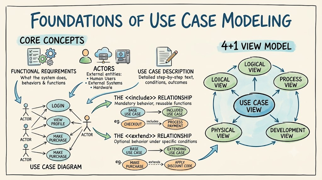
Before diving into the methodology, it is essential to understand the foundational terminology used in use case modeling:
Functional Requirements: Specifications detailing what a system should do (its behaviors and functions), rather than how it should do it (which are non-functional requirements like performance or security).
Actor: Any external entity (a human user, an external system, or a hardware device) that interacts with the system to achieve a goal.
Use Case Diagram: A visual, high-level representation of the system’s functionality, showing actors and their interactions with specific use cases.
Use Case Description: A detailed, text-based specification of a single use case, outlining the step-by-step interactions, conditions, and outcomes.
The <<include>> Relationship: Indicates that a base use case mandatorily incorporates the behavior of another use case. It is primarily used to identify and extract reusable system functions.
The <<extend>> Relationship: Indicates that an extending use case optionally adds behavior to a base use case under specific conditions.
The 4+1 View Model: An architectural framework where the Use Case View acts as the central, unifying perspective that guides the design of the other four views: Logical, Process, Development, and Physical.
Use cases are not merely documentation; they are active tools that drive the entire software development lifecycle. They assist in mapping system requirements through five key functions.
Business stakeholders often write requirements in broad, ambiguous natural language (e.g., "The system needs to handle user checkouts quickly and securely"). Use cases distill these wordy definitions into a clear set of "jobs" or measurable results. By forcing the team to look at the system from the "outside looking in," use cases provide a concrete, standardized format for designers without losing the core business value or important contextual details.
One of the most expensive mistakes in software development is discovering a missing requirement after the code has been written. Use cases bring gaps in requirements to the forefront at the very beginning of a project. By walking through the step-by-step logic of a user's journey, stakeholders and developers quickly identify missing information, edge cases, or misunderstood workflows. Clarifying these gaps early saves significant time and money, and allows teams to discard low-value requirements before resources are committed.
In complex architectures, the 4+1 View Model is frequently utilized to manage system complexity. In this model, the Use Case View is the central pillar. Because use cases define the actual value delivered to the user, all other architectural views rely on them for guidance:
Logical View: Ensures internal classes and objects support the use case flows.
Process View: Ensures workflows, concurrency, and synchronization meet the use case's performance needs.
Development View: Maps the use cases to specific code modules and subsystems.
Physical View: Ensures the deployment configuration and hardware can handle the use case execution.
While a use case diagram provides a necessary high-level overview of system scope, it lacks the depth required for actual coding. Use case descriptions provide the granular detail system designers need. A complete description includes:
Preconditions: The state the system must be in before the use case can begin (e.g., User must be logged in).
Main Flow (Basic Flow): The standard, step-by-step sequence of events for a successful, normal execution.
Extensions (Alternative Flows): Optional steps, error handling, or alternative paths (often modeled with <<extend>>) that deviate from the main flow.
End Conditions (Postconditions): The state of the system after the use case successfully completes (e.g., Order is saved to the database, and a receipt is emailed).
Use cases extend their value far beyond the design phase, becoming vital tools for project management and quality assurance:
Workload Management: Once use cases are prioritized by business value, they can be assigned to development teams. Progress is easily tracked based on the tangible user value delivered per sprint or milestone.
Test Case Development: Because use cases precisely capture success criteria and alternative flows from the user's perspective, they are the perfect starting point for generating comprehensive test cases and QA procedures.
Architectural Guidance: By analyzing <<include>> relationships across multiple use cases, software architects can easily identify reusable components, services, or microservices early in the design phase.
To visualize how these concepts come together, below are two PlantUML examples.
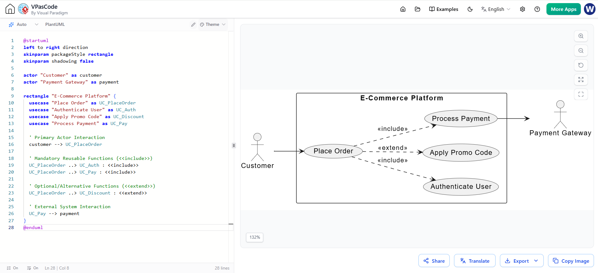
This diagram illustrates the high-level scope of an E-Commerce system. It demonstrates the use of <<include>> for mandatory, reusable processes (Authentication, Payment Processing) and <<extend>> for optional behaviors (Applying a Discount).
@startuml
left to right direction
skinparam packageStyle rectangle
skinparam shadowing false

actor "Customer" as customer
actor "Payment Gateway" as payment

rectangle "E-Commerce Platform" {
  usecase "Place Order" as UC_PlaceOrder
  usecase "Authenticate User" as UC_Auth
  usecase "Apply Promo Code" as UC_Discount
  usecase "Process Payment" as UC_Pay

  ' Primary Actor Interaction
  customer --> UC_PlaceOrder

  ' Mandatory Reusable Functions (<<include>>)
  UC_PlaceOrder ..> UC_Auth : <<include>>
  UC_PlaceOrder ..> UC_Pay : <<include>>

  ' Optional/Alternative Functions (<<extend>>)
  UC_PlaceOrder ..> UC_Discount : <<extend>>

  ' External System Interaction
  UC_Pay --> payment
}
@enduml
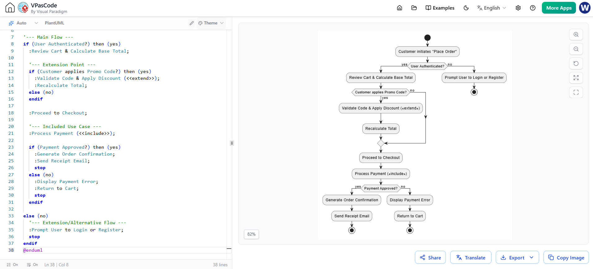
While the use case diagram shows the scope, the activity diagram maps the Main Flow and Extensions mentioned in the detailed specifications. This helps developers understand the exact logic and decision points required to fulfill the "Place Order" use case.
@startuml
skinparam shadowing false

start
:Customer initiates "Place Order";

'--- Main Flow ---
if (User Authenticated?) then (yes)
  :Review Cart & Calculate Base Total;

  '--- Extension Point ---
  if (Customer applies Promo Code?) then (yes)
    :Validate Code & Apply Discount (<<extend>>);
    :Recalculate Total;
  else (no)
  endif

  :Proceed to Checkout;

  '--- Included Use Case ---
  :Process Payment (<<include>>);

  if (Payment Approved?) then (yes)
    :Generate Order Confirmation;
    :Send Receipt Email;
    stop
  else (no)
    :Display Payment Error;
    :Return to Cart;
    stop
  endif

else (no)
  '--- Extension/Alternative Flow ---
  :Prompt User to Login or Register;
  stop
endif
@enduml
Use cases are much more than simple diagrams; they are the foundational blueprint for successful system design. By distilling ambiguous business needs into concrete functional requirements, they ensure that every line of code written serves a distinct user purpose.
Through early gap identification, they save projects from costly late-stage pivots. Through the 4+1 view model, they align the entire technical architecture with business goals. Finally, by providing detailed specifications and clear success criteria, they seamlessly transition the project from design into development and rigorous testing. Mastering the use of use cases is not just a best practice in requirements gathering—it is the key to building systems that truly deliver value to the end user.

