For years, the Agile community and the UML (Unified Modeling Language) world have been portrayed as philosophical opposites. Agile champions working software, adaptive planning, and lightweight communication. UML, especially in its early enterprise adoptions, became synonymous with heavyweight upfront design, rigid documentation, and waterfall-style modeling.
This dichotomy is a false choice. When applied pragmatically, UML is not a documentation burden but a visual communication tool. And when anchored to user stories, UML becomes a catalyst for shared understanding, reduced ambiguity, and evolutionary design.
This article provides a comprehensive, practical guide to integrating UML with Agile development through the user story approach. You’ll learn which diagrams add real value, how to map them to user stories, when to create them, and how to keep them alive without violating Agile principles.
The Agile Manifesto values working software over comprehensive documentation. It does not say no documentation. The key word is comprehensive. Agile teams need just enough documentation to align cross-functional members, reduce rework, and sustain delivery velocity.
UML, at its core, is a standardized visual language for representing system structure, behavior, and interactions. In an Agile context, it should be:
Purpose-driven: Created only when it solves a real communication or design problem.
Just-in-time: Drafted during refinement or sprint planning, not months in advance.
Collaborative: Sketched on whiteboards, digital canvases, or lightweight tools during conversations.
Disposable or Evolving: Treated as living artifacts that change as the system evolves, or discarded once their communicative purpose is served.
This approach aligns with Agile Modeling principles: travel light, model with a purpose, use the simplest artifact that works, and update models incrementally.
User stories are the primary requirement artifact in Agile. They follow the classic format:
As a [role], I want [feature] so that [benefit].
Stories are intentionally lightweight. They capture who, what, and why, leaving the how open for conversation during backlog refinement, sprint planning, and implementation. Acceptance criteria (often in Given/When/Then format) define boundaries and testability.
However, stories frequently encounter friction when they involve:
Complex business workflows
Multi-system integrations
State-dependent behavior
Non-obvious error paths or edge cases
Shared domain concepts across multiple stories
This is where UML shines. Rather than replacing user stories, UML complements them by making implicit complexity explicit, enabling faster alignment, and surfacing hidden assumptions before code is written.
Not all UML diagrams are equally useful in an Agile workflow. Teams should adopt a minimal, high-leverage subset aligned to common story types:
| Diagram Type | Best For | Agile Story Fit |
|---|---|---|
| Activity Diagram | Workflows, business processes, decision paths, parallel steps | Stories describing multi-step user journeys or backend processes |
| Sequence Diagram | Message flow, API interactions, service-to-service calls, timing | Integration stories, microservice boundaries, third-party API usage |
| State Machine Diagram | Entity lifecycle, status transitions, event-driven behavior | Stories involving objects that change state (orders, accounts, tickets) |
| Class Diagram (Lightweight) | Domain model evolution, shared vocabulary, relationships | Stories requiring new entities, refactoring, or cross-team domain alignment |
| Component/Deployment Diagram | System boundaries, infrastructure, service topology | Architecture spikes, DevOps alignment, migration stories |
Rule of thumb: If a story can be fully understood and tested through conversation and acceptance criteria alone, skip the diagram. If ambiguity, risk, or complexity emerges, draft the simplest UML sketch that resolves it.
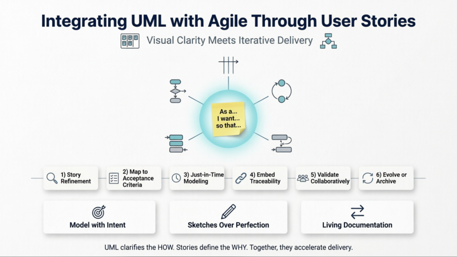
Integrating UML with user stories requires a lightweight, repeatable workflow. Follow this six-step cycle:
During backlog grooming, the Product Owner, developers, and QA collaboratively read the story. When complexity surfaces, pause and ask: “Can we sketch this out?” Use a whiteboard or digital canvas to draft an activity, sequence, or state diagram. Focus on flow, not notation perfection.
Each branch, loop, or message in the diagram should map to one or more acceptance criteria. Use the diagram to:
Identify missing edge cases
Derive test scenarios
Clarify system boundaries
Align on error handling strategies
Create diagrams at the iteration level, not the program level. If a story spans multiple sprints, model incrementally. Update diagrams as implementation reveals new constraints. Avoid upfront enterprise modeling unless justified by compliance or architecture runway needs.
Link diagrams directly to user stories in your Agile toolchain:
Attach images or markdown diagrams to user stories in your tracking system
Use team wiki or documentation pages with bidirectional links
Tag diagrams with story identifiers for traceability
Store diagrams-as-code in the same repository as feature branches
Treat diagrams as conversation starters, not contracts. Review them in refinement sessions, pair programming, or mob programming. Encourage QA to challenge flows, and UX to validate user paths. If a diagram doesn’t spark discussion, it’s likely not adding value.
After implementation:
Update diagrams if they reflect the final system
Archive them if they were only used for alignment
Delete obsolete versions to prevent documentation rot
Automate diagram generation from tests or code where feasible
Let’s walk through a realistic example to see UML and user stories in action.
User Story:
As a registered user, I want to reset my password so I can regain access to my account if I forget it.
Initial Acceptance Criteria:
User can request a reset link via email
Link expires after 24 hours
User sets a new password meeting complexity rules
Old sessions are invalidated after reset
During refinement, the team sketches an activity diagram covering:
User enters email → System validates existence → Sends token → User clicks link → Enters new password → System validates & updates → Redirects to login
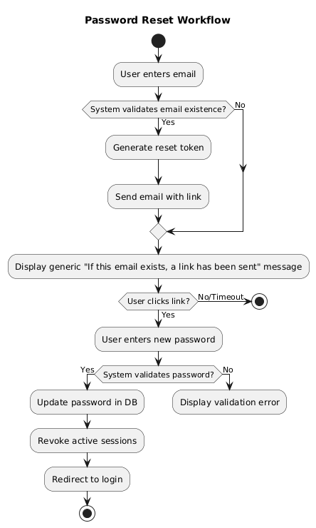
This reveals a missing edge case: What if the email doesn’t exist? Should we leak account existence? The team decides on a generic message for security, updating acceptance criteria accordingly.
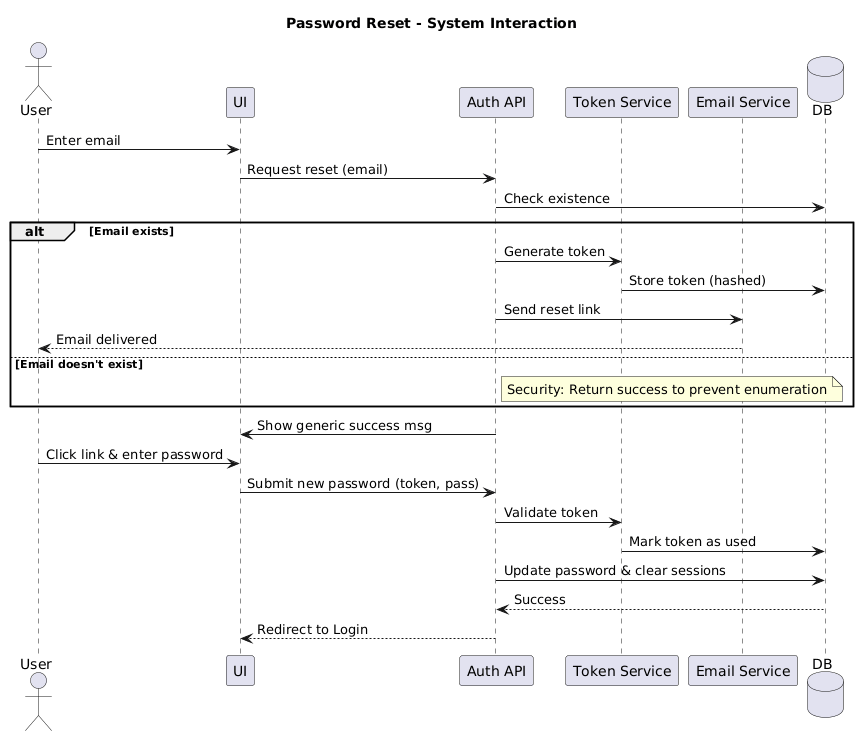
The backend lead drafts a sequence diagram showing the flow between system components:
UI → Auth API → Token Service → Email Service → DB → UI
@startuml
title Password Reset – System Interaction

actor User
participant "UI" as UI
participant "Auth API" as API
participant "Token Service" as Token
participant "Email Service" as Email
database "DB" as DB

User -> UI : Enter email
UI -> API : Request reset (email)
API -> DB : Check existence
alt Email exists
API -> Token : Generate token
Token -> DB : Store token (hashed)
API -> Email : Send reset link
Email –> User : Email delivered
else Email doesn't exist
note right of API: Security: Return success to prevent enumeration
end
API -> UI : Show generic success msg

User -> UI : Click link & enter password
UI -> API : Submit new password (token, pass)
API -> Token : Validate token
Token -> DB : Mark token as used
API -> DB : Update password & clear sessions
DB –> API : Success
API –> UI : Redirect to Login
@enduml
This clarifies service boundaries, timeout handling, and idempotency requirements. QA uses it to design integration tests.
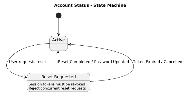
The security engineer notes that account status changes during reset:
Active → Reset Requested → Reset Completed
@startuml
title Account Status – State Machine

[*] –> Active

state Active {
}

state "Reset Requested" as Reset {
Reset : Session tokens must be revoked
Reset : Reject concurrent reset requests
}

Active –> Reset : User requests reset
Reset –> Active : Reset Completed / Password Updated
Reset –> Active : Token Expired / Cancelled

@enduml
The state diagram highlights that concurrent requests should be rejected, and session tokens must be revoked on transition. This becomes a technical task and test scenario.
All three diagrams are lightweight, story-scoped, and directly traceable. They live in the sprint’s documentation space, linked to the user story ticket. After implementation, the sequence diagram is kept as living documentation; the others are archived.
Model with Intent: Only create a diagram if it resolves ambiguity, aligns stakeholders, or reduces rework.
Prefer Sketches Over Perfection: Use informal notation during conversations. Polish only when documenting shared architecture.
Cross-Functional Ownership: Product, QA, and UX should participate in diagramming, not just developers.
Align with Definition of Done: Include “diagram reviewed and linked” as a DoD checklist item only when diagrams were created for the story.
Use Diagrams to Drive Automation: Map activity/sequence diagrams to behavior-driven scenarios or contract tests for living documentation.
Scale Thoughtfully: In scaled Agile environments, use UML for architectural enablers and cross-team dependencies, not individual story delivery.
| Pitfall | Impact | Mitigation |
|---|---|---|
| Upfront Enterprise Modeling | Wastes time, resists change, becomes obsolete | Scope to sprint-level stories; model just-in-time |
| Siloed Architect Modeling | Misalignment, knowledge hoarding, delays | Co-create in refinement sessions; rotate facilitation |
| Treating Diagrams as Contracts | Rigidity, fear of updating, documentation debt | Explicitly label as “working drafts”; update or discard freely |
| Over-Notation Perfectionism | Slows delivery, distracts from conversation | Use informal sketches; standardize only for cross-team reference |
| Ignoring Maintenance | Stale diagrams mislead new team members | Embed in DoD; automate updates; archive obsolete versions |
Modern practices make Agile UML frictionless when approached thoughtfully:
| Approach | Agile Fit |
|---|---|
| Diagrams-as-Code | Version-controlled, CI/CD friendly, merges easily with source changes |
| Collaborative Canvas | Real-time refinement, stakeholder friendly, supports remote collaboration |
| Integrated Wikis | Linked to stories, searchable, team-accessible, supports bidirectional traceability |
| AI-Assisted Generation | Rapid prototyping, draft generation from stories, accelerates initial sketching |
Pro Tip: Store diagram definitions in plain text format alongside user story documentation or code. They render automatically in many version control interfaces and CI/CD pipelines, ensuring diagrams stay in sync with the codebase.
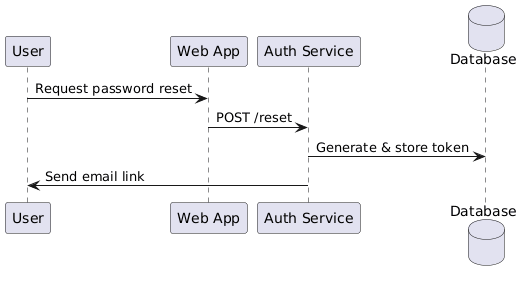
Example diagram notation snippet in a story’s documentation:
@startuml
participant User as U
participant "Web App" as UI
participant "Auth Service" as API
database Database as DB
U -> UI : Request password reset
UI -> API : POST /reset
API -> DB : Generate & store token
API -> U : Send email link
@enduml
UML and Agile are not competitors; they are complementary lenses on the same goal: delivering valuable software sustainably. User stories capture the why and what. UML clarifies the how and structure. When integrated thoughtfully, UML transforms from a documentation tax into a collaboration catalyst.
The key is discipline: model only when it adds value, keep it lightweight, tie it directly to user stories, and treat diagrams as living conversation artifacts rather than static deliverables. In doing so, Agile teams gain clarity without ceremony, alignment without bureaucracy, and evolutionary design without upfront speculation.
In modern engineering, the question isn’t UML vs. Agile. It’s which visualization, at which moment, for which conversation, will help us deliver better software faster? Anchor that answer to your user stories, and you’ll find UML not just compatible with Agile, but indispensable to it.