In modern AI-assisted software engineering, developers face a critical choice in how they interact with Large Language Models (LLMs). This case study focuses on Approach 2: The UML-Mediated Workflow, contrasting it briefly with the more common direct approach to establish context.
Approach 1: Direct Prompting (The "Fluency" Path)
The user describes requirements in natural language, and the LLM generates code immediately.
Pros: Extremely fast; leverages the LLM’s massive training data on code; ideal for scripts and prototypes.
Cons: Prone to "hallucinated" architecture; brittle at scale (>500 lines); difficult to maintain as complexity grows because there is no intermediate design artifact.
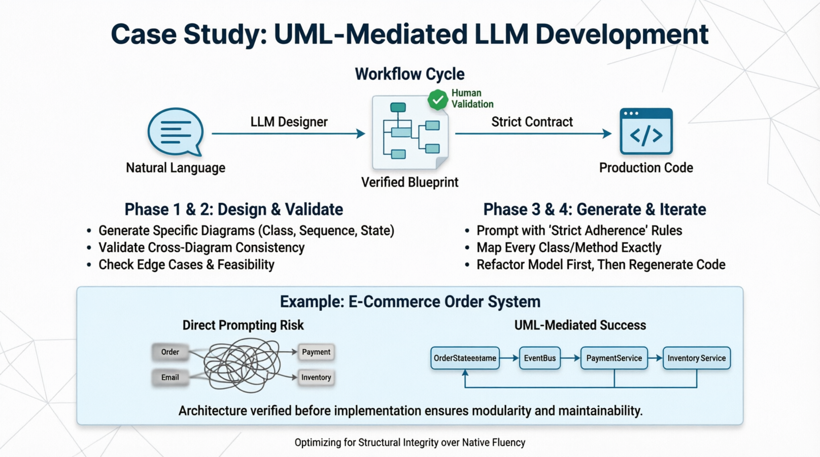
Approach 2: UML-Mediated (The "Structural Integrity" Path)
The user describes requirements, the LLM generates a formal UML model (Class, Sequence, or State diagrams), the human validates the model, and then the LLM generates code based strictly on that validated model.
Pros: Enforces architectural correctness; separates "what" from "how"; scalable to enterprise complexity; creates a verifiable contract before coding begins.
Cons: Higher upfront cognitive load; requires human validation skills; slower time-to-first-line-of-code.
Thesis: While Approach 1 optimizes for speed, Approach 2 optimizes for correctness and maintainability. This guide demonstrates how to execute Approach 2 effectively, overcoming the LLM's native bias toward direct coding.
LLMs are trained primarily on GitHub repositories and Stack Overflow—datasets dominated by final code, not the design process that preceded it. Consequently, when asked to do Option 2, LLMs often treat UML as "decorative text" rather than a strict specification.
The Solution: You must force the LLM into a "Designer Mode" where it is explicitly penalized for skipping the modeling step or generating inconsistent diagrams. The workflow below is designed to counteract this bias.
Do not ask for code yet. Ask for a specification.
Guideline: Use specific diagram types for specific problems. Do not ask for "a UML diagram." Be precise.
Class Diagrams: For data structure, relationships, and API contracts.
Sequence Diagrams: For complex interactions, async flows, and API integrations.
State Machine Diagrams: For order processing, user authentication flows, or game logic.
Prompt Template (Phase 1):
"Act as a Senior Software Architect. I need to build a [System Description].
Do NOT write any code yet.
First, analyze the requirements and generate a [Specific Diagram Type] using PlantUML syntax.
Ensure all relationships, multiplicities, and method signatures are explicitly defined.
List any ambiguities you found in my requirements that need clarification before modeling."
This is where Option 2 succeeds or fails. You must validate the model before proceeding.
Validation Checklist:
Semantic Consistency: Does the Sequence Diagram match the Class Diagram? (e.g., If OrderService calls PaymentGateway in the sequence, does OrderService actually have a dependency on PaymentGateway in the class diagram?)
Completeness: Are edge cases represented? (e.g., What happens if payment fails? Is there an error state in the State Machine?)
Feasibility: Can this actually be implemented in the target tech stack? (e.g., Don't model synchronous blocking calls for a high-throughput event system).
Tooling Tip: Use tools like PlantUML Server, Mermaid Live Editor, or VS Code extensions to render the text-based UML instantly for visual verification.
Now, treat the UML as a strict contract, not a suggestion.
Prompt Template (Phase 3):
"Here is the VALIDATED PlantUML model for our system:
[Paste UML Code]Act as a Senior Backend Engineer. Generate production-ready [Language/Framework] code that STRICTLY adheres to this model.
RULES:
Every class in the diagram must exist in the code with exact naming.
Every relationship (association, inheritance) must be implemented correctly.
Do NOT add methods or fields that are not in the diagram unless they are standard boilerplate (getters/setters).
If you encounter ambiguity in the diagram, STOP and ask me. Do not guess.
Include unit test stubs for each major interaction defined in the Sequence Diagram."
When requirements change, do not edit the code directly. Edit the UML first, re-validate, then regenerate.
Workflow:
Update Requirement → 2. Modify UML → 3. Validate Consistency → 4. Regenerate Code → 5. Diff Check.
Let’s walk through a real-world scenario to illustrate the difference.
"Build an order processing system where users place orders, inventory is checked, payments are processed via Stripe, and confirmation emails are sent. If payment fails, the order should be marked 'Failed' and inventory released."
The LLM might generate a monolithic OrderController with 400 lines of code mixing Stripe API calls, email logic, and database queries. It might forget to release inventory on payment failure because that edge case wasn't emphasized in the prompt. Changing the payment provider later requires hunting through spaghetti code.
Step 1: Generate State Machine Diagram
"Generate a State Machine Diagram for the Order lifecycle including: Created, InventoryReserved, PaymentPending, Paid, Failed, Shipped. Define transitions and triggers."
Step 2: Generate Sequence Diagram
"Generate a Sequence Diagram for the 'Place Order' flow involving: User, OrderService, InventoryService, PaymentGateway, EmailService. Show the rollback flow if PaymentGateway returns error."
Step 3: Human Validation
You notice: The Sequence Diagram shows OrderService calling EmailService synchronously.
Correction: "Update the Sequence Diagram to use an Event Bus/Message Queue for email sending to avoid blocking the payment response."
Step 4: Generate Code
The LLM now generates:
An Order entity with explicit state enum.
An OrderStateMachine class handling transitions.
An OrderService that publishes events instead of calling email directly.
Clean separation of concerns matching the diagram exactly.
Result: A modular, testable, and maintainable system where the architecture was verified before implementation.
| Guideline | Rationale |
|---|---|
| Use Text-Based UML (PlantUML/Mermaid) | LLMs are better at generating valid text syntax than ASCII art or binary formats. Text is also version-controllable. |
| One Diagram Per Concern | Don't cram everything into one massive class diagram. Separate domain models from infrastructure adapters. |
| Annotate Non-Functional Reqs | UML doesn't naturally capture performance/security. Add notes/stereotypes like <<async>>, <<cached>>, or <<rate-limited>> to the diagram. |
| Validate Cross-Diagram Consistency | This is the #1 failure point. Always check that your Sequence Diagrams respect your Class Diagram's interfaces. |
| Treat UML as Executable Spec | If the UML says a method returns void but your business logic needs a result, fix the UML first. Never silently deviate in code. |
| Use "Chain of Thought" Prompting | Ask the LLM to explain its modeling decisions before generating the diagram. "Explain why you chose composition over inheritance here." |
Despite its benefits, UML-Mediated development is not universal. Revert to Approach 1 when:
Building throwaway prototypes or proof-of-concepts.
Working on simple CRUD apps with <5 entities.
The team lacks UML literacy and cannot validate models effectively.
Requirements are extremely volatile and undefined (modeling chaos creates waste).
Option 2 represents a return to software engineering discipline in the age of AI. By inserting a formal, human-verifiable abstraction layer between intent and implementation, we mitigate the LLM's tendency toward fluent but fragile code.
The key takeaway is not just "use UML," but "validate before you generate." The UML is only as good as the human review it receives. When executed correctly, this approach transforms the LLM from a code generator into a true engineering partner, capable of building systems that survive beyond the initial prototype phase.