A practical comparison for software architects and development teams using the C4 model
The C4 model provides a hierarchical approach to visualizing software architecture through four core static structure diagrams: Context, Containers, Components, and Code . However, static diagrams alone cannot fully capture how a system behaves at runtime. This is where the C4 model's supplementary diagrams—Dynamic and Sequence diagrams—add critical value by illustrating runtime interactions and data flows.
This guide compares these two supplementary diagram types, explains their purpose within the C4 framework, and provides practical guidelines for when and how to use each.
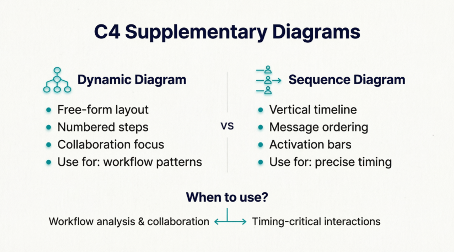
A Dynamic diagram is based on a UML communication diagram (formerly "collaboration diagram") and shows how elements in the static model collaborate at runtime to implement a user story, use case, or feature. It uses numbered interactions to indicate ordering and allows a free-form arrangement of diagram element.
Key characteristics:
Rel($index=1, ...)) to show sequenceA C4-styled Sequence diagram leverages PlantUML's native sequence diagram syntax while reusing C4 model elements (Person, Container, Component) as participants. It emphasizes temporal ordering with vertical lifelines and horizontal messages.
Key characteristics:
->, -->, activate, deactivate){} and closed with Boundary_End()| Goal | How Dynamic/Sequence Diagrams Help |
|---|---|
| Bridge static ↔ dynamic understanding | Show how static components interact at runtime to fulfill requirements |
| Clarify complex interactions | Break down multi-step workflows (e.g., authentication, payment processing) into ordered steps |
| Support onboarding & knowledge transfer | Help new team members trace data flows without reading code |
| Validate architectural decisions | Visualize whether proposed interactions align with scalability, security, or latency goals |
| Communicate with diverse audiences | Provide technical detail for developers while remaining accessible to non-technical stakeholders |
💡 Key Insight: These diagrams are supplementary, not replacements. They should be used sparingly to illustrate interesting or recurring patterns that require complicated interactions .
| Aspect | C4 Dynamic Diagram | C4 Sequence Diagram |
|---|---|---|
| Primary metaphor | Collaboration/network graph | Timeline/lifeline |
| Element positioning | Free-form (spatial optimization) | Fixed vertical lifelines |
| Ordering mechanism | Numbered interactions ($index) |
Implicit top-to-bottom flow |
| Best for | Showing who talks to whom in a workflow | Showing exact message timing & activation |
| PlantUML syntax | C4_Dynamic.puml + indexed Rel() |
C4_Sequence.puml + native sequence syntax |
| Boundary syntax | Standard { } blocks |
Boundary without { } + Boundary_End() |
| Flexibility | Higher (rearrange for clarity) | Lower (strict temporal layout) |
| Learning curve | Lower for C4 users | Higher (requires PlantUML sequence knowledge) |
Dynamic Diagram Style (free-form, numbered):
Rel_R(c1, c2, "Submits credentials to", "JSON/HTTPS") // Step 1
Rel(c2, c3, "Calls isAuthenticated() on") // Step 2
Rel_R(c3, c4, "select * from users...", "JDBC") // Step 3
Sequence Diagram Style (timeline, lifelines):
c1 -> c2: Submits credentials to [JSON/HTTPS]
activate c2
c2 -> c3: Calls isAuthenticated() on
activate c3
c3 -> c4: select * from users... [JDBC]
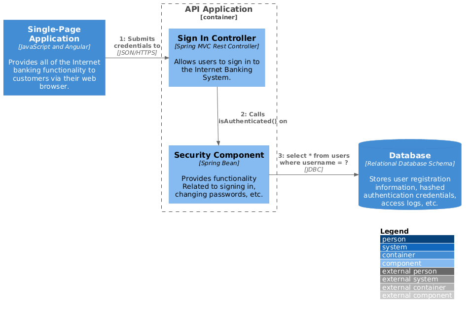
@startuml
!include https://raw.githubusercontent.com/plantuml-stdlib/C4-PlantUML/master/C4_Dynamic.puml
LAYOUT_WITH_LEGEND()
ContainerDb(c4, "Database", "Relational Database Schema", "Stores user registration information, hashed authentication credentials, access logs, etc.")
Container(c1, "Single-Page Application", "JavaScript and Angular", "Provides all of the Internet banking functionality to customers via their web browser.")
Container_Boundary(b, "API Application") {
Component(c3, "Security Component", "Spring Bean", "Provides functionality Related to signing in, changing passwords, etc.")
Component(c2, "Sign In Controller", "Spring MVC Rest Controller", "Allows users to sign in to the Internet Banking System.")
}
Rel_R(c1, c2, "Submits credentials to", "JSON/HTTPS")
Rel(c2, c3, "Calls isAuthenticated() on")
Rel_R(c3, c4, "select * from users where username = ?", "JDBC")
@enduml
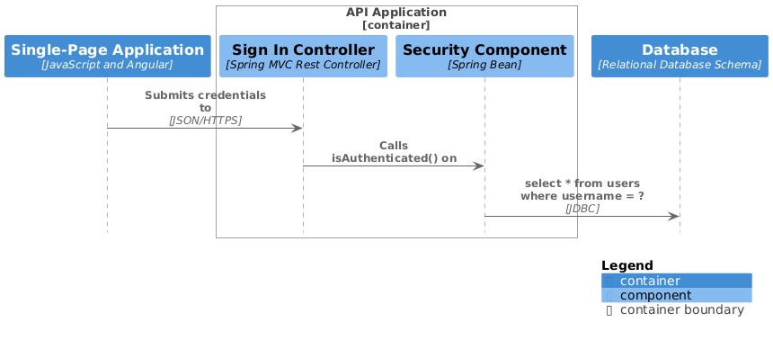
@startuml
!include https://raw.githubusercontent.com/plantuml-stdlib/C4-PlantUML/master/C4_Sequence.puml
Container(c1, "Single-Page Application", "JavaScript and Angular", "Provides all of the Internet banking functionality to customers via their web browser.")
Container_Boundary(b, "API Application")
Component(c2, "Sign In Controller", "Spring MVC Rest Controller", "Allows users to sign in to the Internet Banking System.")
Component(c3, "Security Component", "Spring Bean", "Provides functionality Related to signing in, changing passwords, etc.")
Boundary_End()
ContainerDb(c4, "Database", "Relational Database Schema", "Stores user registration information, hashed authentication credentials, access logs, etc.")
Rel(c1, c2, "Submits credentials to", "JSON/HTTPS")
Rel(c2, c3, "Calls isAuthenticated() on")
Rel(c3, c4, "select * from users where username = ?", "JDBC")
SHOW_LEGEND()
@enduml
"JSON/HTTPS", "JDBC")LAYOUT_WITH_LEGEND() or SHOW_LEGEND() for clarity.puml) in version control alongside source codeNeed to show runtime behavior?
│
├─► Is precise timing/activation critical? ──► Yes ──► Use Sequence Diagram
│ │
│ └─► No ──► Continue
│
├─► Is spatial layout/clarity more important than timeline? ──► Yes ──► Use Dynamic Diagram
│
├─► Does the workflow have complex branching/parallelism? ──► Yes ──► Prefer Dynamic Diagram
│
├─► Is your team more familiar with UML sequences? ──► Yes ──► Use Sequence Diagram
│
└─► Default recommendation: Start with Dynamic Diagram (more C4-native, flexible)
Both C4 Dynamic and Sequence diagrams serve the same fundamental purpose: making runtime behavior visible within the C4 model's static architecture framework. The choice between them isn't about which is "better," but which better serves your audience, use case, and team workflow.
🎯 Final Recommendation: Start with a Dynamic diagram for most use cases. Only reach for a Sequence diagram when you genuinely need PlantUML's advanced sequence features or your team requires strict temporal semantics. And always remember: diagrams are communication tools, not artifacts for their own sake .