
SysML v2 represents a foundational evolution of the Systems Modeling Language. While SysML v1 was built as a UML profile optimized for graphical diagrams, SysML v2 is a standalone modeling language designed for modern Model-Based Systems Engineering (MBSE). It introduces a formal textual syntax, native requirement modeling, explicit semantics, and a clear separation between the underlying model and its visual representations.
This guide breaks down the key differences, explains the rationale behind each change, and provides practical examples to help systems engineers transition from v1 to v2.
| Aspect | SysML v1 | SysML v2 | Why It Matters |
|---|---|---|---|
| Primary Representation | Diagram-centric. The diagram is the model. | View-centric. Diagrams are derived views of a single underlying model. | Enables model reuse, eliminates duplication, and ensures consistency across stakeholder perspectives. |
| Architecture Foundations | Relies on "pillars" (Structural, Behavioral, Parametric, Requirements). | Maps pillars to modular Capabilities that can be enabled/disabled per project. | Improves extensibility, reduces bloat, and allows domain-specific tailoring. |
| Notation | Graphical only. | Dual notation: Formal textual syntax + graphical views. | Enables version control, automated analysis, scripting, and seamless tool interoperability. |
In v1, you manually draw a Block Definition Diagram (BDD) and update it when the model changes. In v2, you define the model textually, then generate a General View that automatically renders the structure. If you change the model, all dependent views update instantly.
SysML v2 refines terminology to eliminate ambiguity and align with formal modeling principles.
| SysML v1 | SysML v2 | Rationale |
|---|---|---|
Block |
Part Definition |
"Part" emphasizes reusable structural definitions rather than UML-class inheritance baggage. |
Part Property |
Part |
Simplifies instance modeling; a part is a concrete occurrence of a part definition. |
Connector |
Connection |
Focuses on the relationship itself rather than the diagrammatic line. |
Port |
Port / Interface |
Ports are now strictly typed and paired with first-class interface definitions. |
SysML v1 allowed untyped "standard" UML ports, which often led to ambiguous connections. SysML v2 removes them. Every port must be explicitly typed via an interface or used as a proxy port.
SysML v2 Textual Example:
// 1. Define the types
item def HouseholdOutlet;
item def HouseholdDevice;

interface def ApplianceConnection {
    end port outlet : HouseholdOutlet;
    end port device : HouseholdDevice;
}

part def CoffeeMaker {
    port powerIn : ApplianceConnection;
}
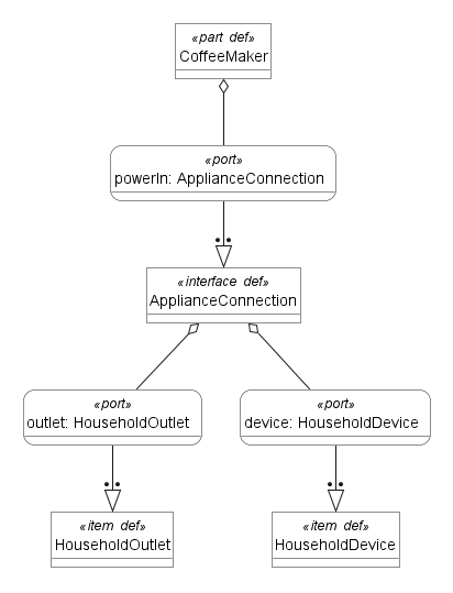
Note: In v2, interfaces are specialized connections. Every interface is also a valid connection, but not vice versa.
v1: You draw a connector, then separately attach an ItemFlow to specify what passes through it.
v2: Flow properties are defined directly within the connection, reducing modeling steps and improving traceability.
SysML v2 Example:
// 1. Define missing types
item def TankPort;
item def EnginePort;
item def MaterialFlow;
connection def FuelLine {
    end part source : TankPort;
    end part target : EnginePort;

    // 2. flow syntax
flow Fuel : MaterialFlow from source to target;
}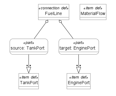
The flow Fuel is now an intrinsic property of FuelLine, not a separate annotation.
SysML v1 relied on implicit generalization arrows in diagrams. v2 provides explicit syntax, improving model clarity, tool validation, and reuse.
SysML v2 Example:
part def Vehicle { }
part def ElectricVehicle specializes Vehicle { }
part def HybridVehicle    specializes Vehicle { }
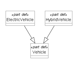
The specializes keyword makes the relationship machine-readable and traceable across tools.
v1: Requirements are modeled using «Requirement» stereotypes on blocks or classes, requiring custom profiles and often breaking traceability.
v2: Requirements are first-class modeling elements with built-in relationships (satisfies, verifies, refines, derives).
SysML v2 Example:
// 1. Define the Performance category
attribute def Performance;

requirement req_001 {
// 2. Use 'doc'
doc /* The pump shall deliver a minimum flow rate of 10 L/min. */

// 3. Use 'attribute' keyword
attribute category = Performance;
}

part def HydraulicPump {
// 4. Use 'satisfy' followed by the requirement name
satisfy req_001;
}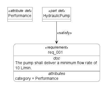
No stereotypes. No custom profiles. Native traceability from day one.
| v1 Diagram | v2 Equivalent | Key Differences |
|---|---|---|
| Block Definition Diagram (BDD) | General View |
Can mix Part Definitions and Part instances. Driven by viewpoints, not fixed canvas rules. |
| Internal Block Diagram (IBD) | Interconnection View |
Focuses on granular connection topology, interface binding, and flow routing. Supports layered interconnection modeling. |
Instead of drawing a diagram, you define a Viewpoint (rules/filters) and then generate a View:
package ArchitectureModel {

// 1. Define the blueprints (Definitions)
part def Engine;
part def Transmission;
connection def ShaftLink;

// 2. Create the actual system parts (Usages)
part e1 : Engine;
part t1 : Transmission;
connection s1 : ShaftLink;

// 3. Define a viewpoint to constrain and organize views
viewpoint def ArchitecturalView {
requirement filterRequirement {
doc "Filter elements by types: Part, Connection, and Requirement."
}
}

// 4. Define a view based on the viewpoint
view SystemArchitectureView : ArchitecturalView {
satisfy filterRequirement;

// Expose the defined elements in this view
expose e1;
expose t1;
expose s1;
}
}
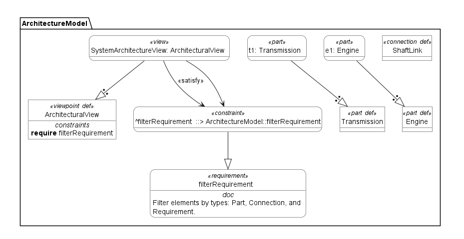
This ensures that stakeholders always see consistent, model-driven representations tailored to their needs.
SysML v2 introduces formal constructs to model how systems behave and evolve over time:
| Construct | Purpose | Example Use Case |
|---|---|---|
Individual Occurrence Definition |
Tracks a unique instance through its lifecycle (e.g., serial numbers, manufacturing batches). | Modeling a specific aircraft tail number N12345 with maintenance history. |
Snapshot Definition |
Captures the exact state of a system at a discrete point in time. | Recording sensor readings, configuration states, or fault conditions at T=0. |
Time Slice Definition |
Models a continuous time range during which specific behaviors or constraints apply. | Analyzing battery degradation between T=0h and T=5000h. |
SysML v2 Conceptual Example:
occurrence def BatteryCycle_01 {
    doc /* Lifecycle of a battery cell from initial state to end-of-life after 5,000 hours. */
    snapshot InitialState {
        doc /* Battery is at full charge and nominal capacity at time zero. */
        attribute T = 0;
    }
    timeslice DegradationPhase {
        doc /* Gradual capacity degradation due to cyclic stress and aging. */
        // Define duration within the timeslice
        attribute startT = 0;
        attribute endT = 5000;
    }
    snapshot EndOfLife {
        doc /* Battery capacity has degraded below acceptable threshold. */
        attribute T = 5000;
    }
}
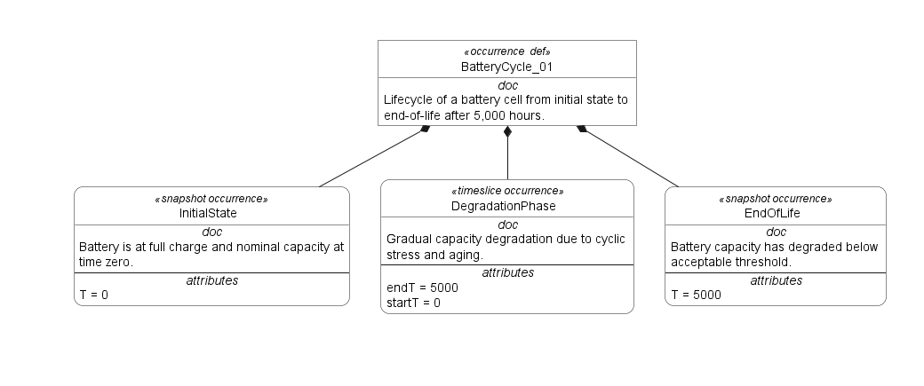
These constructs enable precise temporal analysis, digital twin alignment, and lifecycle traceability.
Enables stakeholder-specific model projections without duplicating elements.
Supports automated filtering, layout rules, and consistency checks.
Example: A safety engineer sees only failure modes and verifies relationships; a manufacturing engineer sees only Part instances and Connection routing.
SysML v2 integrates constraint validation and requirement verification directly into the language.
Tools can run model checkers, evaluate OCL-like constraints, and flag requirement gaps automatically.
Example: constraint def MaxTemp { condition = sensor.temperature <= 85.0; } can be automatically verified against simulation or design data.
package SafetyProjections {
	private import ScalarValues::*;
	// 1. Define the Viewpoint (The "Rules" for the view)
	viewpoint def SafetyViewpoint {
		doc /* Filter only parts with 'safety_critical = true' and their relationships. */
	}

	// 2. Define the System Parts
	part def BrakeSystem {
		attribute isSafetyCritical : Boolean = true;
	}

	part def Radio {
		attribute isSafetyCritical : Boolean = false;
	}

	// 3. The View (The actual stakeholder projection)

	view BrakeSafetyView {
		viewpoint safety_vp : SafetyViewpoint;
		expose BrakeSystem;
		// Note: Radio is NOT exposed here, filtering the model for the stakeholder.
	}
}
package ThermalVerification {
	private import ScalarValues::*;
	private import ISQ::*;

	constraint def MaxTempLimit {
		in temp : Real;
		temp <= 85.0
	}

	requirement <'R1'> OperatingTempRequirement {
		doc /* The processor must operate below 85 degrees celsius. */

		assert constraint MaxTempLimit {
			in temp = processor.currentTemp;
		}
	}

	part processor {
		attribute currentTemp : Real;
	}

	satisfy OperatingTempRequirement by processor;

}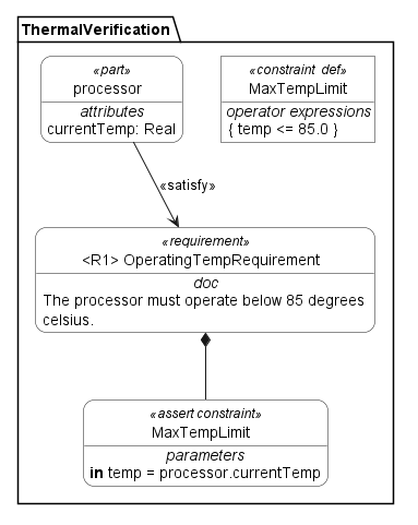
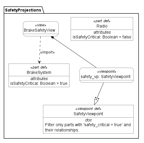
viewpoint allows you to define how to see the model separately from what is in the model.constraint def uses a formal condition block. This isn't just text; it's a logical expression that an analysis tool can execute to flag a "Violation" if the temperature exceeds 85.0.Would you like to see how to define an Analysis Case to run a simulation that feeds data into that MaxTempLimit constraint?
✅ Single Source of Truth: Model-view separation eliminates diagram-model drift.
✅ Tool Interoperability: Standardized textual syntax enables Git-based workflows and CI/CD for MBSE.
✅ Reduced Ambiguity: Explicit inheritance, native requirements, and typed ports prevent modeling errors.
✅ Scalable Complexity: Capabilities and views let you model large systems without visual clutter.
✅ Future-Proof: Aligns with digital engineering, AI-assisted modeling, and formal verification trends.
Map Diagrams to Views: Treat v1 diagrams as starting points for v2 General and Interconnection Views.
Adopt Textual Syntax Gradually: Start with core structures (Part Definition, Connection, Requirement) before leveraging advanced temporal constructs.
Refactor Stereotypes: Replace «Requirement» or «Flow» stereotypes with native v2 constructs.
Enforce Interface Typing: Audit all ports and replace untyped connectors with explicit interface def blocks.
Leverage Tool Support: Use modern SysML v2-compliant tools (e.g., Catia Magic v2, Cameo Systems Modeler 2024+, open-source KerML/SysML v2 toolchains) that auto-generate views from text.
SysML v2 is not merely an update; it is a reimagining of systems modeling for the digital engineering era. By shifting from diagram-centric workflows to model-driven views, introducing a formal textual syntax, and making requirements, inheritance, and flows first-class citizens, SysML v2 delivers unprecedented traceability, scalability, and automation potential.
For teams transitioning from v1, the learning curve is primarily conceptual: think in terms of models, views, and capabilities rather than diagrams and stereotypes. Once adopted, SysML v2 enables rigorous, interoperable, and future-ready MBSE practices that align with industry standards, regulatory demands, and next-generation digital twin ecosystems.
💡 Next Step: Start by modeling a small subsystem (e.g., a power distribution unit) using SysML v2 textual syntax. Generate
GeneralandInterconnection Views, attach nativeRequirementelements, and validate connections usinginterface def. This hands-on approach will quickly solidify the paradigm shift.

