Software systems are complex, and no single diagram can capture every aspect that different stakeholders care about. Developers need structural clarity, testers require execution flows, business analysts focus on functionality, and DevOps teams care about hardware and deployment.
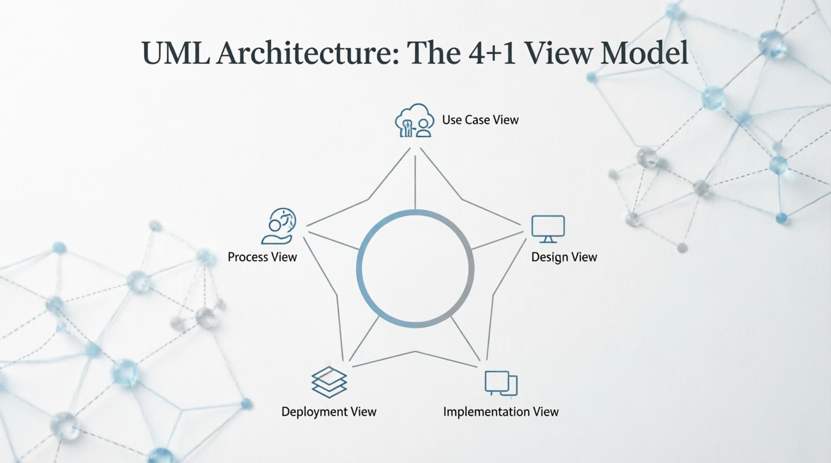
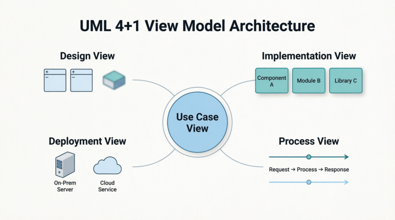
UML (Unified Modeling Language) addresses this challenge by providing a standardized, multi-perspective approach to architecture. The framework you described aligns precisely with the industry-standard 4+1 View Model (originally proposed by Philippe Kruchten). It organizes architecture into four structural/behavioral views centered around a fifth use case-driven view, ensuring every stakeholder gets the right information without overwhelming them with unnecessary details.
This guide breaks down the core concepts, provides a real-world example, and offers actionable guidelines and tips to help you apply UML architecture effectively in modern software projects.
| Concept | Description |
|---|---|
| Multi-Perspective Modeling | Architecture is not a single blueprint. It’s a set of complementary views, each targeting specific concerns and audiences. |
| Use Case View (The "+1") | Acts as the glue that connects all other views. It defines system functionality through user goals and scenarios, driving requirements and validation. |
| View Independence & Consistency | Each view can be modeled independently but must remain traceable and consistent with the others. Changes in one view often ripple into others. |
| Static vs. Dynamic Elements | UML separates structural (static) modeling like classes/components from behavioral (dynamic) modeling like flows, states, and interactions. |
| Stakeholder-Centric Communication | UML diagrams are communication tools first, documentation second. They translate technical complexity into audience-appropriate abstractions. |
Purpose: Captures what the system does from an end-user or external system perspective.
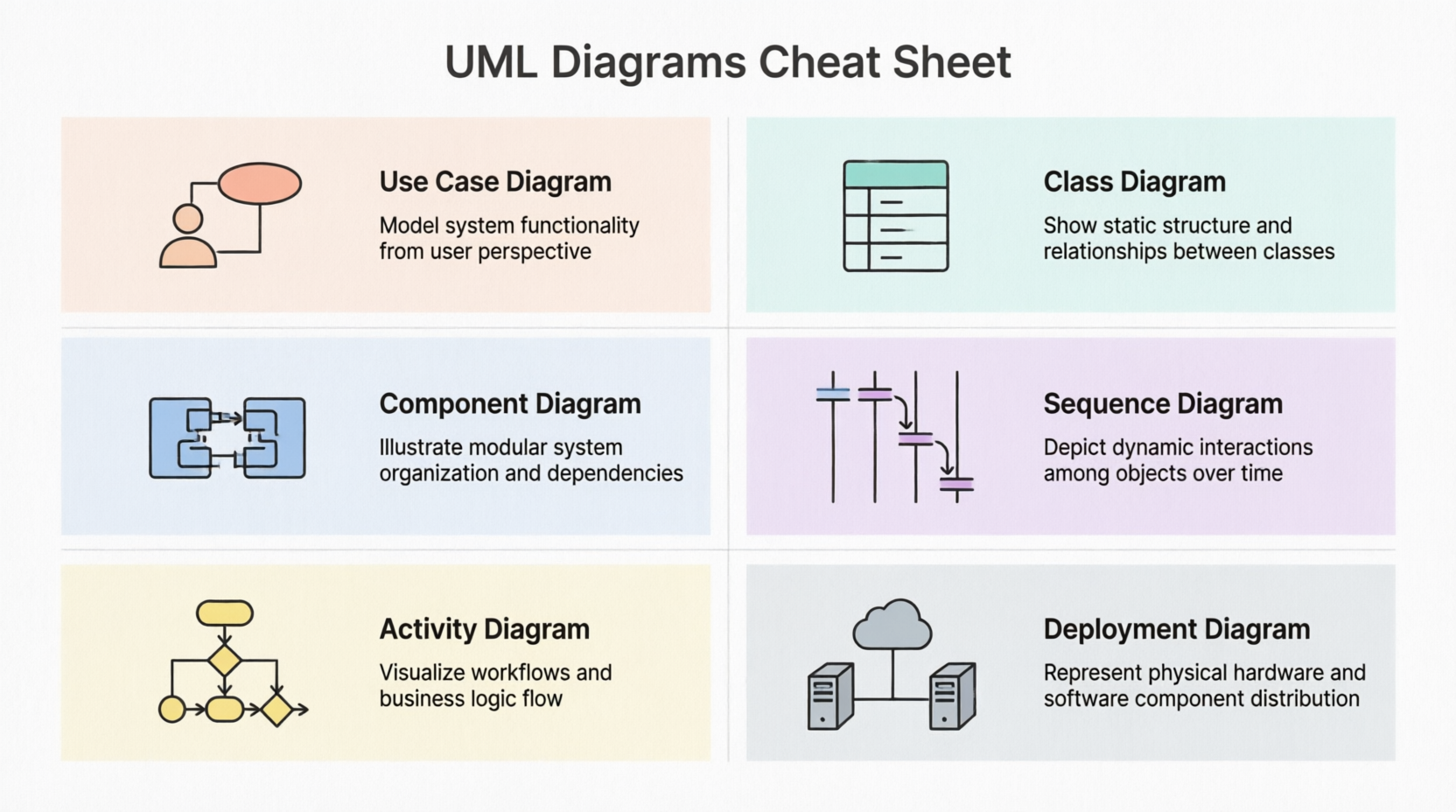
Key UML Diagrams: Use Case Diagram, Activity Diagram (for scenario flows), Sequence Diagram (for critical paths).
Audience: Business analysts, product owners, testers, all stakeholders.
Why it matters: Drives requirements, guides test cases, and validates that other architectural views actually deliver user value.
Purpose: Represents the static structure and object-oriented design of the system.
Key UML Diagrams: Class Diagram, Object Diagram, Package Diagram, State Machine Diagram.
Audience: Software developers, solution architects, domain experts.
Why it matters: Defines data models, relationships, inheritance, interfaces, and design patterns. Forms the blueprint for coding.
Purpose: Shows how the system is organized in code, modules, libraries, and build artifacts.
Key UML Diagrams: Component Diagram, Package Diagram (with build dependencies), File/Module structures.
Audience: Developers, build/release engineers, CI/CD pipeline designers.
Why it matters: Maps logical design to physical code organization, clarifies module boundaries, dependencies, and reusability.
Purpose: Models dynamic behavior, execution flow, threading, synchronization, performance, and fault tolerance.
Key UML Diagrams: Sequence Diagram, Activity Diagram, Communication Diagram, State Diagram, Timing Diagram.
Audience: Backend developers, system engineers, performance/QA testers.
Why it matters: Reveals how components interact at runtime, handles concurrency, async operations, and resource contention. Uses the same structural elements from the Design view but focuses on their runtime behavior.
Purpose: Illustrates the hardware infrastructure, network topology, and how software artifacts are deployed across physical or cloud nodes.
Key UML Diagrams: Deployment Diagram, Composite Structure Diagram, Node/Artifact mappings.
Audience: DevOps engineers, network architects, system administrators, cloud engineers.
Why it matters: Defines servers, containers, databases, load balancers, communication protocols, and scaling strategies. Ensures the system can run reliably in production.
| View | How It Applies | UML Diagrams Used |
|---|---|---|
| Use Case | Customers browse products, add to cart, checkout, make payments, and track orders. | Use Case Diagram, Activity Diagram |
| Design | User, Product, ShoppingCart, Order, Payment classes with associations, aggregations, and interfaces like IPaymentGateway. |
Class Diagram, Object Diagram |
| Implementation | Frontend React app, Backend REST API, payment-service component, inventory-db module, shared utils-library. |
Component Diagram |
| Process | Checkout flow: cart validation → payment async call → inventory reservation → order confirmation. Handles concurrency for flash sales. | Sequence Diagram, Activity Diagram, State Diagram |
| Deployment | Web servers behind CDN, API gateway, Kubernetes pods for microservices, managed PostgreSQL cluster, Redis cache node, AWS S3 for images. | Deployment Diagram |
How they connect:
The Checkout use case drives the Sequence Diagram (Process), which operates on Order and Payment classes (Design), packaged into the payment-service component (Implementation), deployed across API-Gateway → Payment-Pod → DB-Cluster nodes (Deployment). Change one, and you validate impact across the others.
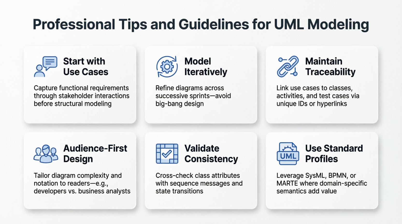
Start with Use Cases – Always begin by capturing user goals. They anchor every other view and prevent over-engineering.
Model Iteratively – Architecture evolves. Use lightweight, version-controlled UML models that grow with sprints/releases.
Maintain Traceability – Link diagrams explicitly. e.g., tag a class with <<implements>> a component, or map a sequence step to a deployment node.
Keep Audience in Mind – Don’t show deployment details to business analysts, and don’t drown developers in hardware topology.
Validate Consistency – Regularly cross-check that class relationships match component boundaries, and that runtime flows align with deployed infrastructure.
Use Standard Profiles & Stereotypes – Extend UML cleanly with <<service>>, <<microservice>>, <<container>>, etc., to match modern architectures.
Avoid Diagram Overload – One diagram = one clear question. Split complex flows into layered or scoped diagrams.
| Challenge | Solution |
|---|---|
| Diagrams go out of sync with code | Use UML tools with code generation/reverse engineering (PlantUML, StarUML, Enterprise Architect). Treat UML as living documentation. |
| Too many arrows/relationships | Apply the "Rule of 7±2". Group related elements, use packages/nested diagrams, and hide low-level details until needed. |
| Unclear runtime behavior | Pair static Class Diagrams with Sequence/State Diagrams. Use activity partitions (swimlanes) to clarify responsibilities. |
| Cloud/Container mapping is messy | Use Deployment Diagrams with <<container>>, <<pod>>, <<service mesh>> stereotypes. Show network zones explicitly. |
| Stakeholders find UML confusing | Start with Use Case + Activity diagrams for non-technical audiences. Add technical views only when required. |
| Version control for UML | Store diagrams as text (PlantUML, Mermaid) in Git. Enables diffs, PR reviews, and CI validation. |
| Performance/Concurrency modeling | Use Timing Diagrams and State Machines to model race conditions, timeouts, and async retries before coding. |
UML architecture isn't about drawing perfect diagrams; it's about communicating the right information to the right people at the right time. The 4+1 View Model provides a structured, stakeholder-driven approach:
Use Case View defines why the system exists.
Design View defines what it's made of.
Implementation View defines how it's built.
Process View defines how it behaves at runtime.
Deployment View defines where it runs.
By aligning UML diagrams with these perspectives, teams reduce ambiguity, catch architectural flaws early, and ensure that business requirements translate cleanly into deployable, maintainable software.
Modern development practices (Agile, DevOps, microservices) haven't replaced UML—they've evolved it. Lightweight, iterative, and tool-integrated UML modeling remains one of the most effective ways to align cross-functional teams, reduce rework, and ship robust systems. Start small, focus on communication over perfection, and let the use cases guide your architecture.
📚 Further Reading:
Kruchten, P. (1995). The 4+1 View Model of Architecture
OMG UML Specification (v2.5.1+)
Applying UML and Patterns by Craig Larman
PlantUML / Mermaid.js documentation for code-based modeling