In the realm of software engineering and systems architecture, complexity is inevitable. Whether you're designing a distributed microservices ecosystem, mapping enterprise business workflows, or aligning technical and non-technical stakeholders on a shared vision, the ability to translate abstract requirements into clear, actionable visuals is what separates successful projects from chaotic ones. This is where the Unified Modeling Language (UML) stands as the industry's definitive blueprint for modern system design.
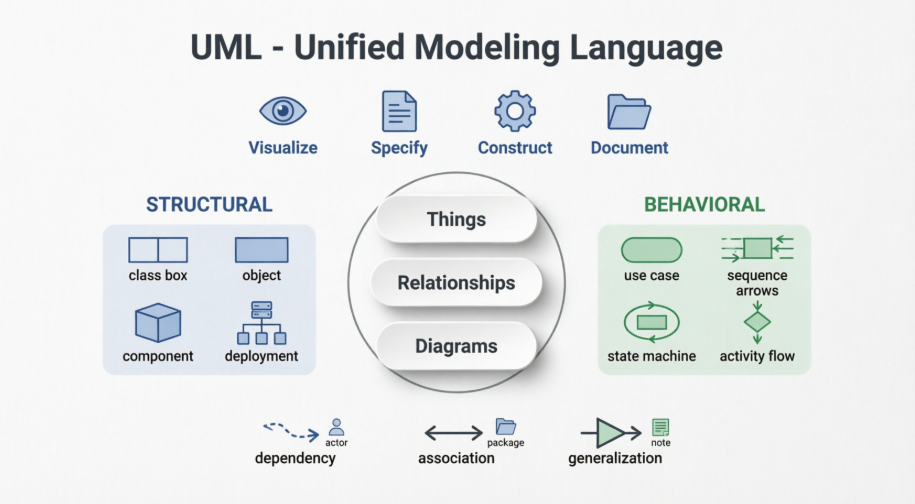
Originally standardized by the Object Management Group (OMG) in the late 1990s, UML is far more than a collection of diagrams—it is a universal, general-purpose visual modeling language built to specify, visualize, construct, and document the artifacts of both software and non-software systems. Rooted in object-oriented analysis and design, UML provides a structured yet adaptable framework that bridges the gap between developers, business analysts, testers, and end-users. Its guiding philosophy is elegantly simple: a well-crafted model eliminates ambiguity, aligns perspectives, and lays the groundwork for scalable, maintainable systems.
At the core of every UML diagram lies its notation system—the foundational symbols, shapes, and connectors that give precise meaning to a model. Much like letters form words and sentences, UML notations serve as the alphabet of system architecture. Without a solid grasp of these basic building blocks, even the most sophisticated diagram risks becoming a confusing jumble of lines and boxes. Mastering UML doesn't begin with drawing complex interaction flows; it begins with understanding the fundamental notations that define structural elements, behavioral dynamics, relationships, and organizational groupings.
This guide serves as a comprehensive primer to UML Basic Notations. We will systematically break down the essential symbols into their core categories, explain their practical applications, and provide actionable guidelines, best practices, and expert tips to help you draft precise, professional-grade models. Whether you're sketching your first class diagram or refining deployment topologies, this foundation will empower you to communicate system designs with clarity, consistency, and confidence—turning complex ideas into universally understood blueprints.
1. Structural Things: The "Nouns" of UML
Structural things define the static part of the model. They represent physical and conceptual elements and are the most widely used notations in UML.
Key Structural Notations
- Class: Represents a set of objects with similar responsibilities. It is depicted as a rectangle divided into compartments:
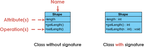
- Top: Class name.
- Middle: Attributes (properties).
- Bottom: Operations (methods).
- Optional Fourth Section: Additional components.
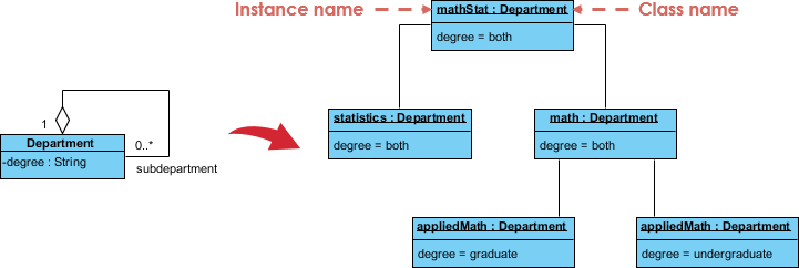
- Object: An instance of a class. It uses the same notation as a class, but the name is underlined to indicate it is a concrete instance at a specific moment.
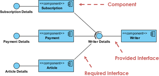
- Interface: Defines a set of operations that specify the responsibility of a class, without implementation. Represented as a circle (often called "lollipop" notation) with the name written below it.
- Use Case: Captures high-level functionalities or goals of a system. Represented as an ellipse with the use case name inside.
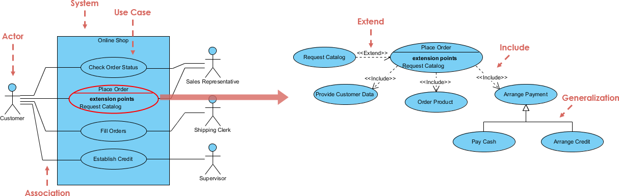
- Actor: An internal or external entity (human, system, or device) that interacts with the system. Depicted as a stick figure.
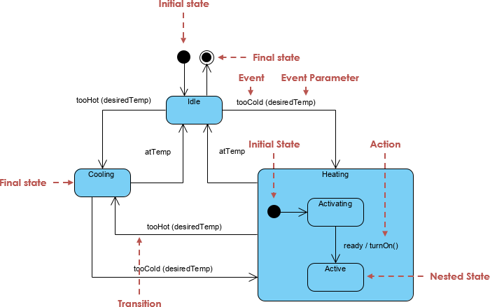
- Initial State: Marks the starting point of a process. Represented as a solid black circle.
- Final State: Marks the termination point of a process. Represented as a solid black circle with a border (bullseye).
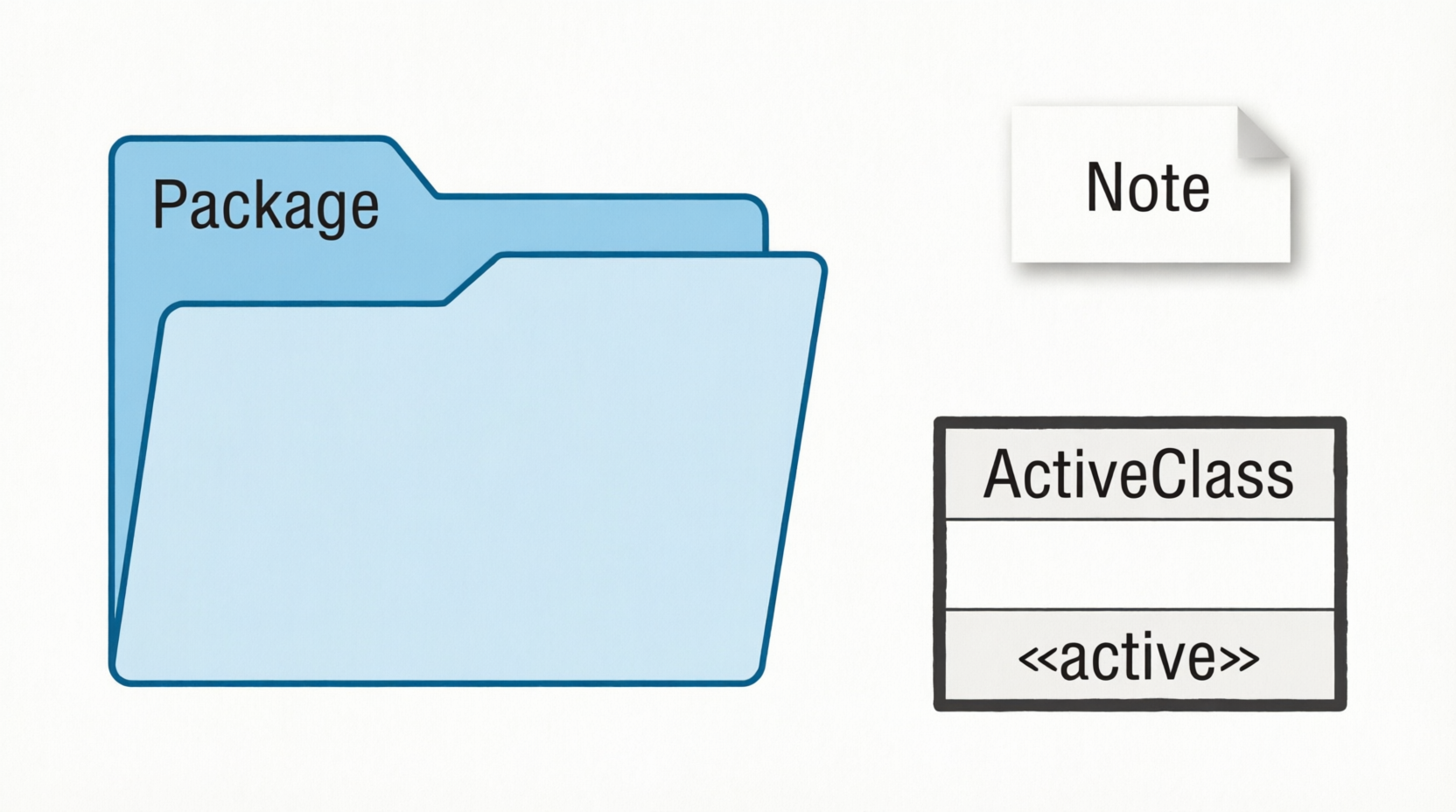
- Active Class: Used to describe concurrent behavior. Looks like a standard class but with a solid, thick border.
- Component: Describes a physical part of a system (e.g., library, file, executable). Shown as a rectangle with a small component icon on the left side.
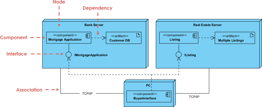
- Node: A physical element that exists at runtime (e.g., server, network device). Represented as a 3D box (cube shape).
Visual Reference: Refer to the generated Structural Notations diagram for visual examples of Class, Object, Interface, Component, and Node symbols.
2. Behavioral Things: The Dynamic Parts
Behavioral things consist of the dynamic parts of UML models, capturing interactions and state changes over time.
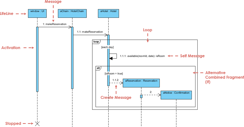
- Interaction: Defined as a behavior consisting of messages exchanged among elements to accomplish a specific task. It is the basis for Sequence and Collaboration diagrams.
- State Machine: Useful when the state of an object in its lifecycle is important. It defines the sequence of states an object goes through in response to events.
Visual Reference: Refer to the generated Use Case and Actor Notations diagram, which also illustrates Initial and Final State symbols essential for behavioral modeling.
3. Grouping and Annotational Things
These notations help organize the model and add necessary context.
- Package: The only grouping thing available. Used to gather structural and behavioral elements together. Represented as a folder/tab shape.
- Note: The only annotational thing. Used to render comments, constraints, or descriptions. Represented as a rectangle with a folded top-right corner.
Visual Reference: Refer to the generated Grouping and Annotational Notations diagram for Package, Note, and Active Class symbols.
4. Relationships: Connecting the Blocks
Relationships give proper meaning to a UML model by showing how elements are associated.
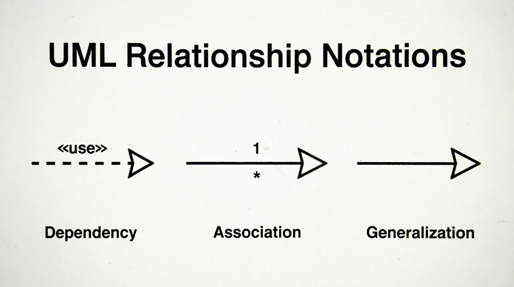
- Dependency: A relationship where a change in one element affects another. Represented by a dashed arrow. The arrow points to the independent element; the tail is at the dependent element.
- Association: A set of links connecting elements. Represented by a solid or dashed line. It may have arrows to indicate direction and multiplicity markers (e.g.,
1, *) to show how many objects participate.
- Generalization: Describes the inheritance (parent-child) relationship. Represented by a solid line with a hollow triangular arrowhead pointing to the parent element.
- Extensibility: Mechanisms to extend UML capabilities when standard notations are insufficient:
- Stereotypes: Represent new elements.
- Tagged Values: Represent new attributes.
- Constraints: Represent boundaries or rules.
Visual Reference: Refer to the generated Relationship Notations diagram for Dependency, Association, and Generalization symbols.
💡 Key Concepts, Guidelines, and Tips & Tricks
Key Concepts
- Visualization is Paramount: The visual effect of the UML diagram is the most important part of the modeling process. Notations must be used correctly to convey the intended meaning.
- Static vs. Dynamic: Structural notations represent the "static" framework (what exists), while behavioral notations represent the "dynamic" flow (how it behaves). A complete model requires both.
- Abstraction Levels: Use notations to abstract complex systems. For example, a Use Case diagram provides a high-level view of functionality, while a Class diagram provides detailed structural specifications.
Guidelines for Drawing
- Start with a Conceptual Model: Before drawing diagrams, understand the real-world entities and their relationships. This ensures your notations accurately reflect the system.
- Use Meaningful Names: Every element (Class, Use Case, Actor, etc.) should have a clear, descriptive name. A well-named diagram is self-explanatory.
- Keep It Simple: Avoid clutter. Only include necessary properties and relationships. Use notes to explain complex logic rather than overcrowding the diagram with text.
- Consistent Style: Use standard notations consistently. If you use a solid border for an Active Class, ensure all Active Classes in the model follow this convention.
Tips & Tricks
- Underline Objects: Always underline object names to distinguish them from class blueprints. This is a quick visual cue for readers.
- Leverage Packages: For large systems, use Package notations to group related elements. This makes navigation and understanding of complex models much easier.
- Use Generalization Wisely: Inheritance can quickly become complex. Use Generalization arrows carefully and avoid deep inheritance hierarchies that are hard to maintain.
- Dependency vs. Association: Remember that Dependency is weaker than Association. Use Dependency when an element merely "uses" another temporarily, and Association when there is a structural link.
- Extensibility for Custom Needs: If standard UML doesn't cover a specific requirement, use Stereotypes and Tagged Values to extend the notation without breaking the standard.
- Notes Are Your Friend: Use Note notations liberally to document constraints, business rules, or implementation details that don't fit into the structural symbols.
Conclusion
Mastering UML basic notations is far more than memorizing symbols; it is about adopting a universal visual language that transforms abstract requirements into clear, actionable blueprints. By distinguishing between structural foundations and behavioral dynamics, leveraging relationships with precision, and adhering to core guidelines like consistent styling, meaningful naming, and strategic use of packages and notes, you can craft models that are both technically rigorous and highly communicative.
Remember that the true power of UML lies in its ability to align diverse stakeholders, simplify complex systems, and serve as a reliable bridge between design and implementation. A well-drawn diagram doesn’t just document what a system is—it communicates how it behaves, how its parts interact, and how it can evolve.
As you apply these notations to real-world projects, prioritize clarity over complexity, purpose over decoration, and consistency over convention. With deliberate practice, UML will shift from a set of rules to an intuitive design tool, empowering you to architect robust, scalable, and maintainable systems with confidence.