The UML Class Diagram is the most widely used structural diagram in the Unified Modeling Language. It serves as a blueprint for the static structure of a system, depicting classes, their attributes, operations (methods), and the relationships among objects. Unlike behavioral diagrams that show how a system works over time, class diagrams focus on what the system is made of. They are essential during the design phase for object-oriented programming, database modeling, and communicating system architecture to developers, architects, and stakeholders. This guide breaks down the core components, interprets the accompanying diagram, and provides actionable guidelines for creating clear, maintainable class diagrams.
A class is represented as a rectangle divided into three horizontal compartments:
Top: Class name (e.g., Book, Library). Abstract class names are typically italicized.
Middle: Attributes (data fields). Format: visibility name: type [multiplicity]
Bottom: Operations (methods/functions). Format: visibility name(parameters): return type
| Symbol | Visibility | Access Level |
|---|---|---|
+ |
Public | Accessible from anywhere |
- |
Private | Accessible only within the class |
# |
Protected | Accessible within class and subclasses |
~ |
Package | Accessible within the same package |
Association (—): A structural link between classes indicating they interact.
Composition (◆—): Strong "whole-part" relationship. The part cannot exist independently of the whole. (e.g., Library and Book)
Aggregation (◇—): Weak "whole-part" relationship. Parts can exist independently.
Generalization/Inheritance (▷—): "Is-a" relationship. Child class inherits attributes/operations from parent. (e.g., PremiumMember inherits from Member)
Dependency (- - - ▷): Temporary usage. One class depends on another for a specific operation.
Realization (- - - ▷ with dashed line): A class implements an interface.
Defines how many instances of one class relate to instances of another:
1: Exactly one
0..1: Zero or one
0..* or *: Zero or more
1..*: One or more
n..m: Range from n to m
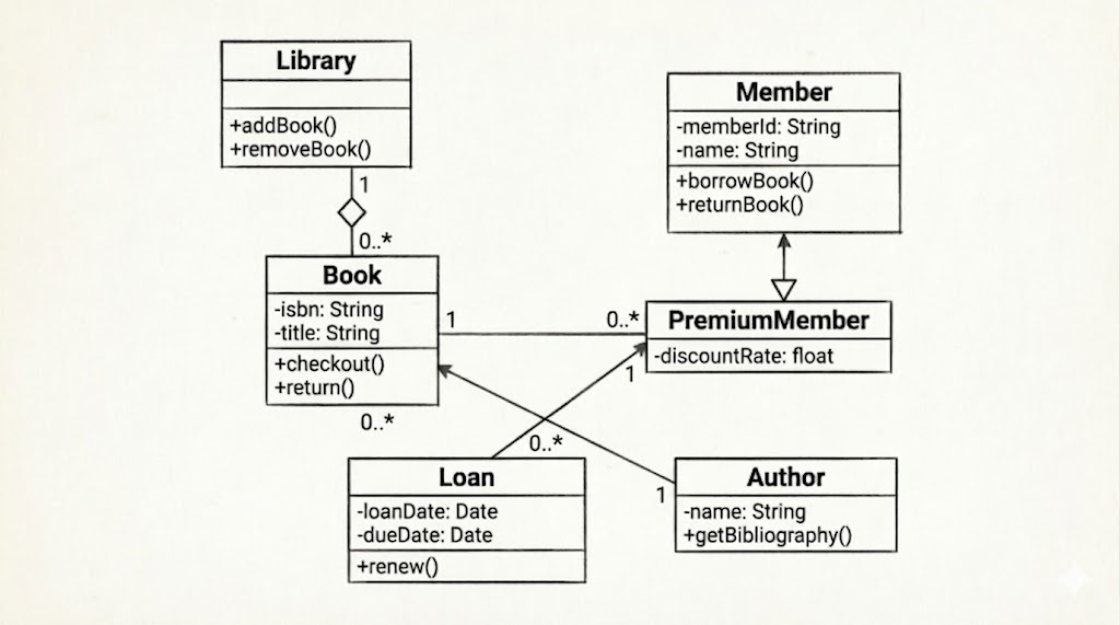
The diagram above models a Library Management Domain. Here's a breakdown of its architecture:
Library & Book (Composition)
Library manages a collection of Book objects.
The filled diamond (◆) indicates composition: books are integral to the library. If the library is decommissioned, its internal catalog ceases to exist in this context.
Multiplicity: 1 Library contains 0..* Books.
Member & PremiumMember (Inheritance)
PremiumMember is a specialized type of Member.
The hollow triangle arrow points to the parent (Member). PremiumMember inherits -memberId and -name, and adds its own -discountRate.
This demonstrates polymorphism and code reuse.
Loan & PremiumMember (Association)
A Loan record is linked to exactly 1 PremiumMember, while a member can have 0..* loans over time.
This tracks borrowing history and enforces business rules (e.g., premium members get extended loan periods).
Book & PremiumMember (Association)
A direct link shows that a Book can be associated with 0..* PremiumMembers, and each association points to 1 specific book. This could represent reservation queues or reading lists.
Author
Author is shown with basic attributes and operation, a many-to-many association would typically connect Book and Author to represent co-authorship.
Focus on the Scope: Don't model every single class in a large system on one diagram. Group by bounded context (e.g., "User Management", "Inventory", "Billing").
Show Only Relevant Details: Avoid cluttering diagrams with every getter/setter or utility method. Highlight domain-critical operations and state-changing methods.
Prefer Composition over Inheritance: Use inheritance only for true "is-a" relationships. Favor composition for "has-a" relationships to reduce coupling and improve maintainability.
Name Classes as Nouns: Classes should represent domain concepts or system entities (e.g., Order, Customer, PaymentProcessor), not actions.
Validate Multiplicities: Ensure numbers reflect real business rules. If a member must have an account, use 1, not 0..1.
Use Stereotypes Sparingly: Apply <<interface>>, <<entity>>, or <<controller>> only when they clarify architectural roles.
Iterate with Stakeholders: Review diagrams with developers and domain experts early. Misunderstood relationships cause costly refactoring later.
Keep Layout Clean: Arrange classes to minimize crossing lines. Group related classes spatially. Use consistent alignment and spacing.
UML Class Diagrams are indispensable for translating abstract requirements into concrete software architecture. By mastering visibility modifiers, relationship types, and multiplicity constraints, teams can create diagrams that serve as both design blueprints and documentation. The figure provided demonstrates how composition, inheritance, and association work together to model real-world domain rules. Remember that a great class diagram is not a rigid contract but a living artifact: refine it as the system evolves, keep it focused on architectural intent, and let it guide clean, maintainable object-oriented implementation.