
Understanding the relationships between UML (Unified Modeling Language) diagrams and Entity-Relationship Diagrams (ERDs) is crucial for effective software design. This guide explores these three essential modeling tools, their purposes, relationships, and optimal sequencing in the development lifecycle.
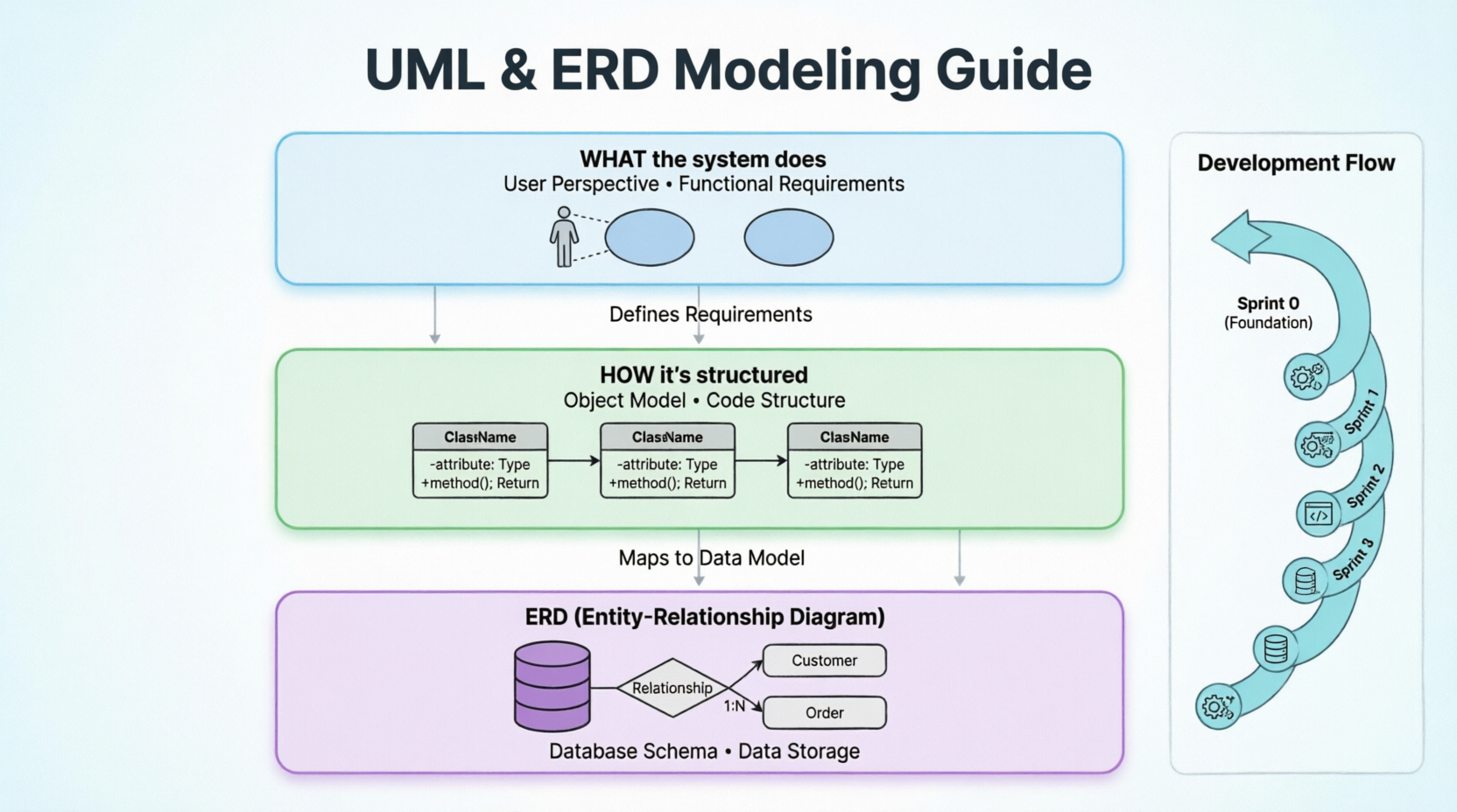
A use case diagram is a behavioral diagram that captures the functional requirements of a system from the user's perspective. It shows:
Actors: Users or external systems interacting with the system
Use Cases: Specific functionalities or goals the system provides
Relationships: Associations between actors and use cases, including includes, extends, and generalizations
Purpose: To define what the system should do without specifying how.
Key Elements:
Actors (stick figures)
Use cases (ovals)
System boundary (rectangle)
Relationships (lines with stereotypes like <>, <>)
A class diagram is a structural diagram that represents the static structure of a system. It shows:
Classes: Blueprints for objects with attributes and methods
Relationships: Associations, aggregations, compositions, inheritances
Multiplicity: How many instances relate to each other
Visibility: Public, private, protected members
Purpose: To define how the system is structured at the code level.
Key Elements:
Classes (rectangles with name, attributes, operations)
Interfaces
Relationships (association, aggregation, composition, inheritance, dependency)
Multiplicity constraints
An ERD is a data modeling diagram that represents the logical structure of a database. It shows:
Entities: Objects or concepts that store data (tables)
Attributes: Properties of entities (columns)
Relationships: How entities connect to each other
Cardinality: One-to-one, one-to-many, many-to-many relationships
Purpose: To define how data is stored and related in the database.
Key Elements:
Entities (rectangles)
Attributes (ovals or listed within entities)
Primary keys (underlined)
Foreign keys
Relationships (diamonds or lines with cardinality notation)
These three diagrams represent different perspectives of the same system:
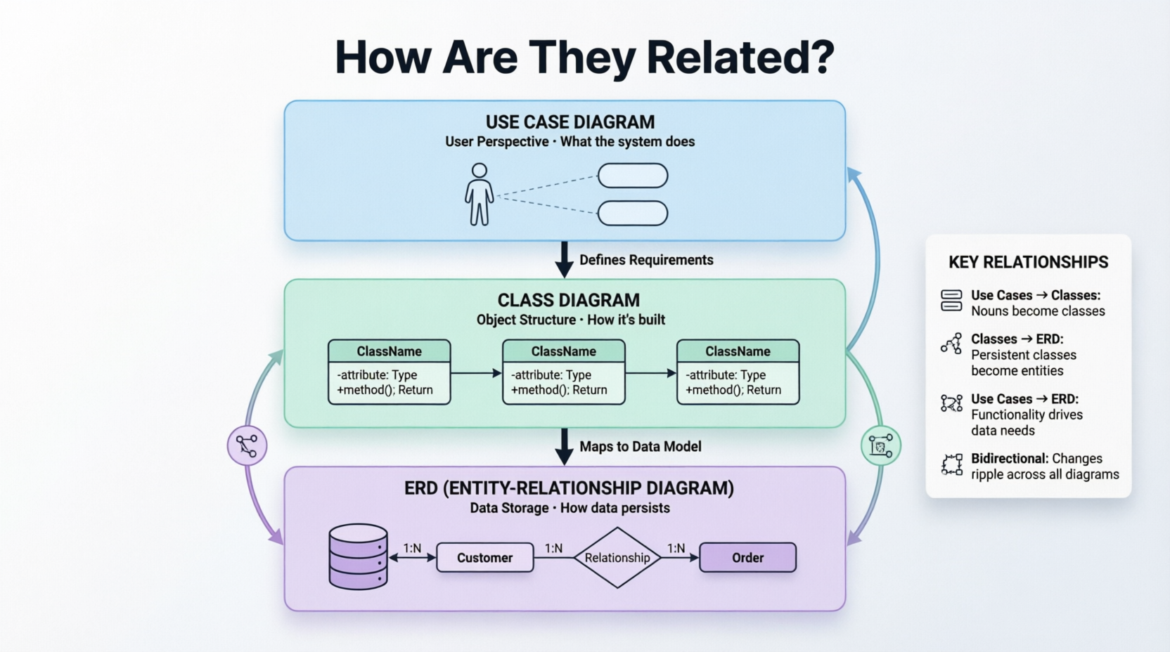
Key Relationships:
Use Case → Class Diagram: Each use case may involve multiple classes collaborating to fulfill the functionality. Classes are identified by analyzing the nouns in use case descriptions.
Class Diagram → ERD: Persistent classes (those that need to be stored) map to entities in the ERD. Class attributes become entity attributes, and class relationships inform database relationships.
Use Case → ERD: Use cases determine what data needs to be captured and persisted, influencing which entities and relationships are necessary.
Bidirectional Influence: Changes in one diagram often require updates in others. For example, adding a new use case might require new classes and new database tables.
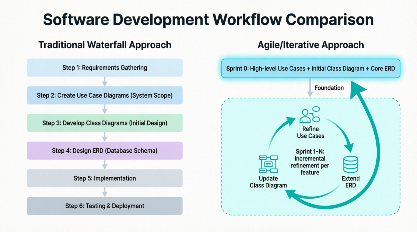
Step 1: Requirements Gathering
    ↓
Step 2: Create Use Case Diagrams (System Scope)
    ↓
Step 3: Develop Class Diagrams (Initial Design)
    ↓
Step 4: Design ERD (Database Schema)
    ↓
Step 5: Implementation
    ↓
Step 6: Testing & Deployment
Sprint 0: High-level Use Cases + Initial Class Diagram + Core ERD
    ↓
Sprint 1-N: Incremental refinement of all three diagrams per feature/use case
Answer: Both approaches exist, but they serve different purposes.
Advantages:
Provides complete architectural overview
Shows all relationships between classes
Helps identify design patterns and potential coupling issues
Essential for understanding the full domain model
Disadvantages:
Can become extremely complex for large systems
Difficult to maintain as the system grows
May overwhelm stakeholders
Best For:
Small to medium-sized systems
Architecture documentation
Onboarding new team members
Final design review
Advantages:
Focused and manageable
Easier to understand and validate
Aligns with agile incremental development
Reduces cognitive load
Disadvantages:
May miss cross-cutting concerns
Requires integration effort later
Potential for inconsistent design across use cases
Best For:
Large, complex systems
Agile development teams
Detailed design discussions for specific features
Early-stage exploration
Create a high-level system-wide class diagram showing major components and their relationships
Create detailed use case-specific class diagrams for complex or critical use cases
Maintain both, ensuring consistency between them
System-Wide Class Diagram (High-Level)
├── Package: User Management
├── Package: Order Processing
├── Package: Inventory
└── Package: Reporting

Use Case-Specific Class Diagrams (Detailed)
├── "Place Order" Use Case → Detailed classes involved
├── "Process Payment" Use Case → Detailed classes involved
└── "Generate Report" Use Case → Detailed classes involved
Answer: Similar to class diagrams, a hybrid approach works best.
Identify core entities that are fundamental to the system (e.g., User, Product, Order)
Design the initial ERD with these core entities and their relationships
Incrementally add entities as new use cases are implemented
Refine relationships as understanding deepens
Database schema changes can be expensive and risky
Early identification of key relationships prevents costly refactoring
Some entities are referenced across multiple use cases
Normalization decisions affect the entire database
Phase 1: Core Domain ERD
├── Identify 5-10 critical entities
├── Define primary relationships
└── Establish normalization rules

Phase 2-N: Incremental Extensions
├── Add new entities for each use case
├── Refine existing relationships if needed
└── Maintain backward compatibility
Create high-level use case diagram covering the entire system scope
Identify major actors and epics
Draft initial class diagram with core domain classes
Design core ERD with fundamental entities
For each use case/feature being implemented:
Refine relevant use cases (add detail, clarify flows)
Create/update use case-specific class diagrams showing classes involved
Update system-wide class diagram with new classes and relationships
Extend ERD with new entities/attributes if persistent data is needed
Implement code and database migrations
Validate consistency across all diagrams
Sprint 0: Foundation
├── Use Cases: Browse Products, Place Order, Manage Account
├── Core Classes: Product, User, Order, Cart
└── Core ERD: products, users, orders, order_items tables

Sprint 1: Implement "Browse Products"
├── Refine "Browse Products" use case
├── Add Category, Review classes
├── Update class diagram
├── Add categories, reviews tables to ERD
└── Implement and test

Sprint 2: Implement "Place Order"
├── Refine "Place Order" use case
├── Add Payment, ShippingAddress classes
├── Update class diagram
├── Add payments, addresses tables to ERD
└── Implement and test

Sprint 3: Implement "Manage Account"
├── Refine "Manage Account" use case
├── Add Wishlist, Notification classes
├── Update class diagram
├── Add wishlists, notifications tables to ERD
└── Implement and test
Keep it simple: Focus on major functionality, not every detail
Use clear actor names: Represent roles, not individuals
Avoid over-complication: Limit <> and <> relationships
Validate with stakeholders: Ensure use cases reflect real user needs
Write use case descriptions: Complement diagrams with detailed narratives
Start with domain-driven design: Identify entities from the problem domain
Apply SOLID principles: Ensure proper separation of concerns
Show only relevant details: Don't clutter with every method
Use consistent naming: Follow language/framework conventions
Review for cohesion and coupling: Minimize dependencies
Normalize appropriately: Balance between 3NF and performance
Define clear primary and foreign keys: Ensure referential integrity
Consider indexing strategy: Plan for query performance
Document business rules: Include constraints and validations
Plan for scalability: Anticipate growth in data volume
Maintain traceability: Link use cases to classes to entities
Use modeling tools: Tools like Enterprise Architect, Lucidchart, or draw.io help maintain consistency
Regular synchronization: Update all diagrams when changes occur
Version control: Treat diagrams as code; store in repository
Team collaboration: Review diagrams together to ensure shared understanding
| Pitfall | Solution |
|---|---|
| Creating diagrams in isolation | Ensure cross-referencing between use cases, classes, and entities |
| Over-engineering early | Start simple; refine incrementally |
| Ignoring non-functional requirements | Consider performance, security, and scalability in design |
| Not updating diagrams | Treat diagrams as living documents |
| Too much detail too soon | Focus on high-level design first |
| Skipping validation | Review with stakeholders and technical team |
| Assuming one-size-fits-all | Adapt approach to project size and complexity |
Enterprise Architect: Comprehensive UML and ERD support
Lucidchart: Web-based, collaborative diagramming
draw.io / diagrams.net: Free, open-source option
Visual Paradigm: Strong UML and database modeling
PlantUML: Code-based diagram generation
MySQL Workbench / pgAdmin: Database-specific ERD tools
Miro / Mural: Collaborative whiteboarding for early-stage diagrams
Use Case Diagrams define what the system does from the user's perspective
Class Diagrams define how the system is structured at the object level
ERDs define how data is stored and related in the database
They are interconnected: Changes in one affect the others
Start with system-wide views, then drill down incrementally
Use a hybrid approach: High-level system diagrams + detailed use case-specific diagrams
Build incrementally but maintain architectural coherence
Keep diagrams synchronized and treat them as living documentation
Adapt to your methodology: Waterfall vs. Agile requires different approaches
Validate continuously with stakeholders and the development team
For most projects, especially in agile environments:
Begin with a high-level use case diagram covering the entire system
Create an initial class diagram identifying core domain classes
Design a core ERD with fundamental entities
For each sprint/use case:
Refine relevant use cases
Create detailed class diagrams for that use case
Update the system-wide class diagram
Extend the ERD as needed
Implement and validate
Continuously maintain consistency across all diagrams
This approach balances comprehensive architectural vision with agile incremental delivery, ensuring both strategic alignment and tactical flexibility.

