
The Unified Modeling Language (UML) is the industry standard for visualizing, specifying, constructing, and documenting the artifacts of software systems. However, to create a modeling language that is both robust and mathematically sound, software engineers had to solve a fundamental philosophical and technical problem: How do you define a modeling language without creating an infinite loop of definitions? (i.e., If a model defines a system, what defines the model?)
To solve this, the Object Management Group (OMG) structured the UML architecture into a four-layer architecture. This framework organizes models based on their levels of abstraction, ensuring a strict, logical hierarchy from the most abstract language definitions down to concrete, executable runtime objects. This guide will explore the mechanics, key concepts, and practical applications of this foundational architecture.
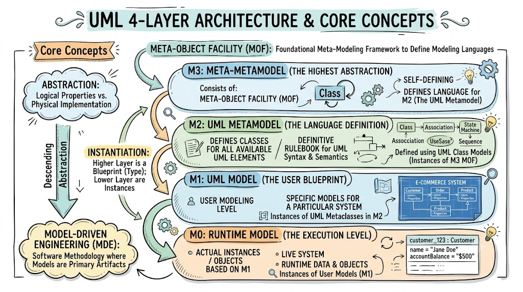
Before diving into the specific layers, it is essential to understand the core concepts that govern this architecture:
Abstraction: The process of separating the logical properties of an element from its physical or specific implementation. The four layers represent a descending scale of abstraction.
Instantiation: The relationship between the layers. Elements in a higher layer define the "blueprint" or "type," and elements in the layer immediately below are the "instances" of those blueprints.
Meta-Object Facility (MOF): The foundational technology at the very top of the hierarchy. It is a meta-modeling framework used to define the structure of modeling languages.
Model-Driven Engineering (MDE): A broader software engineering methodology that relies heavily on this four-layer structure, treating models as primary artifacts of the development process rather than just supplementary diagrams.
The UML architecture is strictly divided into four distinct layers, labeled M3, M2, M1, and M0. The logic behind this structure is that each layer provides the definitions for the elements used in the layer immediately below it.
What it is: The M3 layer is the highest level of abstraction in the UML architecture. It consists of the Meta-Object Facility (MOF).
Its Purpose: It is used to define the language for the level below it. Specifically, it provides the foundational constructs (like "Class," "Attribute," and "Operation" at a purely abstract level) used to model the UML metamodel itself.
Key Characteristic: It is self-defining. The MOF is defined using the MOF.
What it is: This layer contains the classes for all available UML elements (e.g., UML Class, UML Association, UML State Machine).
Its Purpose: It serves as the definitive rulebook for the UML language itself. It dictates what a "Class" is, what relationships are allowed, and the rules governing UML syntax and semantics.
Key Characteristic: The M2 metamodel is largely defined using UML class models (which are instances of the M3 MOF). For example, a word/concept in UML found at the M2 metamodel layer describes the exact types of elements a user is legally allowed to place in their M1 model.
What it is: This is the user modeling level.
Its Purpose: It represents the actual, specific models created by UML users to describe a particular system (e.g., a blueprint for an E-commerce platform, a hospital management system, or a banking API).
Key Characteristic: The elements here (like a specific class named Customer or Order) are instances of the UML metaclasses defined in M2.
What it is: The final, most concrete layer. It represents the actual instances or objects based on the user's model (M1) as they exist in memory during execution.
Its Purpose: It represents the live system. If M1 defines the Customer class, M0 contains the specific object customer_123 with the name "Jane Doe" and account balance "$500".
Key Characteristic: These are the runtime data and objects that the software actually manipulates while running.
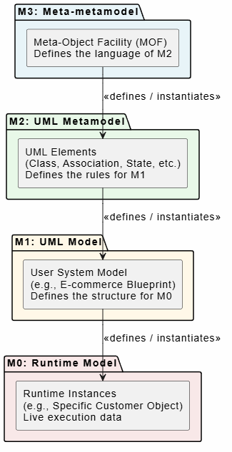
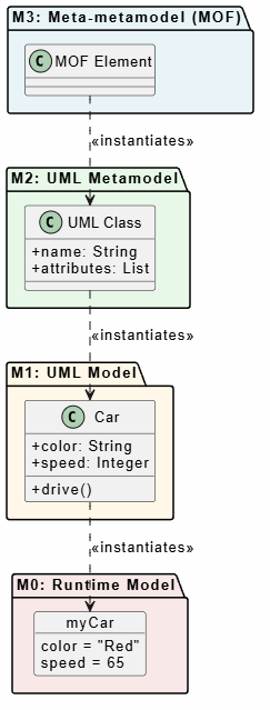
To visualize how these layers interact, below are two PlantUML diagrams.
This diagram illustrates the hierarchical relationship and the "instantiation" (definition) flow from the highest abstraction (M3) down to the runtime objects (M0).
@startuml
skinparam backgroundColor #FEFEFE
skinparam componentStyle rectangle
skinparam defaultFontSize 14

package "M3: Meta-metamodel" #E8F4F8 {
    [Meta-Object Facility (MOF)\nDefines the language of M2] as M3
}

package "M2: UML Metamodel" #E8F8E8 {
    [UML Elements\n(Class, Association, State, etc.)\nDefines the rules for M1] as M2
}

package "M1: UML Model" #FFF8E8 {
    [User System Model\n(e.g., E-commerce Blueprint)\nDefines the structure for M0] as M1
}

package "M0: Runtime Model" #F8E8E8 {
    [Runtime Instances\n(e.g., Specific Customer Object)\nLive execution data] as M0
}

M3 -down-> M2 : <<defines / instantiates>>
M2 -down-> M1 : <<defines / instantiates>>
M1 -down-> M0 : <<defines / instantiates>>

@enduml
This diagram traces a single concept—the idea of a "Class"—as it flows down through the four layers, transforming from an abstract MOF concept into a live runtime object.
@startuml
skinparam backgroundColor #FEFEFE
skinparam classAttributeIconSize 0
skinparam defaultFontSize 13

package "M3: Meta-metamodel (MOF)" #E8F4F8 {
    class "MOF Element" as M3_Element
}

package "M2: UML Metamodel" #E8F8E8 {
    class "UML Class" as M2_Class {
        + name: String
        + attributes: List
    }
}

package "M1: UML Model" #FFF8E8 {
    class "Car" as M1_Car {
        + color: String
        + speed: Integer
        + drive()
    }
}

package "M0: Runtime Model" #F8E8E8 {
    object "myCar" as M0_myCar {
        color = "Red"
        speed = 65
    }
}

M3_Element ..> M2_Class : <<instantiates>>
M2_Class ..> M1_Car : <<instantiates>>
M1_Car ..> M0_myCar : <<instantiates>>

@enduml
The UML four-layer architecture is a masterpiece of software engineering logic. By strictly separating concerns into M3 (Meta-metamodel), M2 (Metamodel), M1 (Model), and M0 (Runtime), it elegantly solves the problem of language definition without falling into infinite regress.
Understanding this hierarchy is crucial for advanced software architects and engineers. It not only clarifies how UML itself is constructed but also forms the bedrock for modern Model-Driven Engineering (MDE) and Model-Driven Architecture (MDA). When you understand that the code running on your server (M0) is just an instantiation of a blueprint (M1), which is governed by UML rules (M2), which are defined by MOF (M3), you gain a profound appreciation for the abstraction that makes complex software design possible.

