
The Unified Modeling Language (UML) 2.0 is the industry-standard language and notation system used to specify, visualize, construct, and document the artifacts of software systems, as well as for business modeling.
A common misconception among beginners is that UML is a strict, step-by-step development methodology (like Agile or Scrum). In reality, UML is a visual vocabulary—a standardized set of tools and notations that you can apply within virtually any development approach. Whether you are mapping out a complex microservices architecture or modeling a simple business workflow, UML provides a universal language that bridges the gap between business analysts, software architects, and programmers.
This comprehensive guide will walk you through the core concepts of UML 2.0, breaking down its structural and behavioral elements, and providing practical PlantUML code examples to help you start visualizing your own systems.
UML 2.0 organizes its 14 diagram types into two fundamental categories based on what they represent:
Structure Diagrams: These represent the static parts of a system. They model the things that exist regardless of time or execution, such as classes, components, data structures, and hardware nodes. They answer the question: What is the system made of?
Behavior Diagrams: These represent the dynamic aspects of a system. They model how the system changes over time, reacts to events, and passes messages. They answer the question: How does the system act and interact?
Structural diagrams are the backbone of object-oriented design. The most common and essential structural diagram is the Class Diagram.
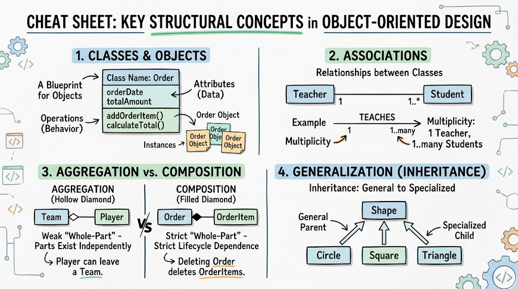
Classes and Objects: A Class is a blueprint describing a set of instances (Objects) that share the same features. In a diagram, a class is a rectangle divided into three compartments: its Name, its Attributes (data/properties), and its Operations (methods/behavior).
Associations: These represent relationships between classes, drawn as solid lines.
Multiplicity: Numbers at the ends of the line (e.g., 1..* or 0..1) dictate how many objects of one class can be linked to another.
Aggregation and Composition: These are specialized "whole-part" relationships symbolized by a diamond on the "whole" end.
Aggregation (Hollow Diamond): A weak relationship. The parts can exist independently of the whole (e.g., a Team and a Player).
Composition (Filled Diamond): A strict, lifecycle-dependent relationship. The parts cannot exist without the whole (e.g., an Order and its OrderItems).
Generalization: The UML term for inheritance. It uses a hollow arrow pointing from the specialized child element to the general parent element.
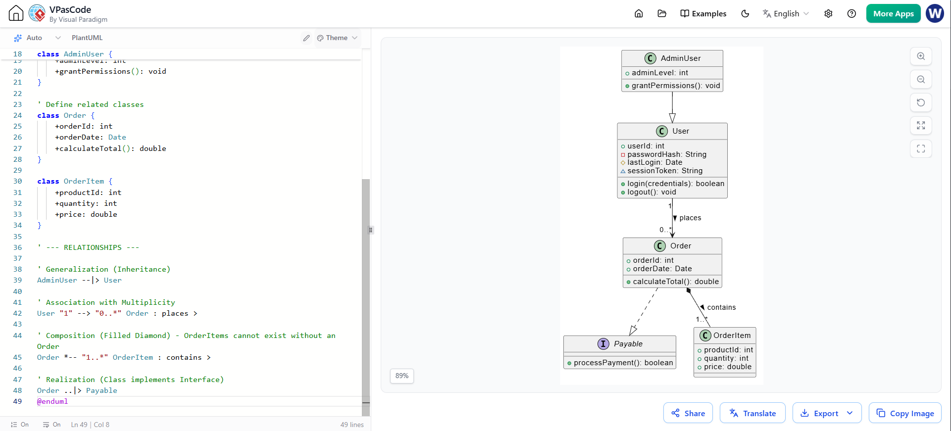
You can copy and paste the code below into any PlantUML renderer (like plantuml.com) to see the visual output.
@startuml
' Define an interface using stereotypes
interface Payable {
    +processPayment(): boolean
}

' Define the Parent Class
class User {
    +userId: int
    -passwordHash: String
    #lastLogin: Date
    ~sessionToken: String
    +login(credentials): boolean
    +logout(): void
}

' Define the Child Class (Generalization/Inheritance)
class AdminUser {
    +adminLevel: int
    +grantPermissions(): void
}

' Define related classes
class Order {
    +orderId: int
    +orderDate: Date
    +calculateTotal(): double
}

class OrderItem {
    +productId: int
    +quantity: int
    +price: double
}

' --- RELATIONSHIPS ---

' Generalization (Inheritance)
AdminUser --|> User

' Association with Multiplicity
User "1" --> "0..*" Order : places >

' Composition (Filled Diamond) - OrderItems cannot exist without an Order
Order *-- "1..*" OrderItem : contains >

' Realization (Class implements Interface)
Order ..|> Payable
@enduml
Behavioral diagrams bring your static models to life by showing how the system operates over time.
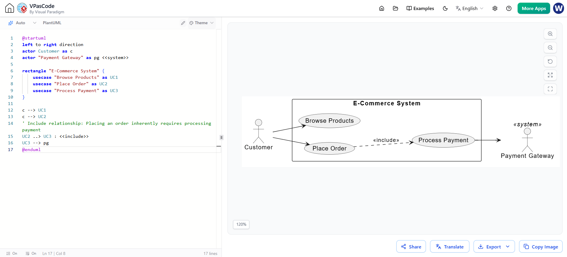
Use Case Diagrams: These describe what a system does for its users (Actors) without explaining how. Actors (stick figures) represent roles outside the system boundary, such as human users or external APIs.
Activity Diagrams: These model the flow of control or data through a process, similar to a advanced flowchart. They use rounded rectangles for Actions, diamonds for Decisions, and bars for parallel processing (forks/joins).
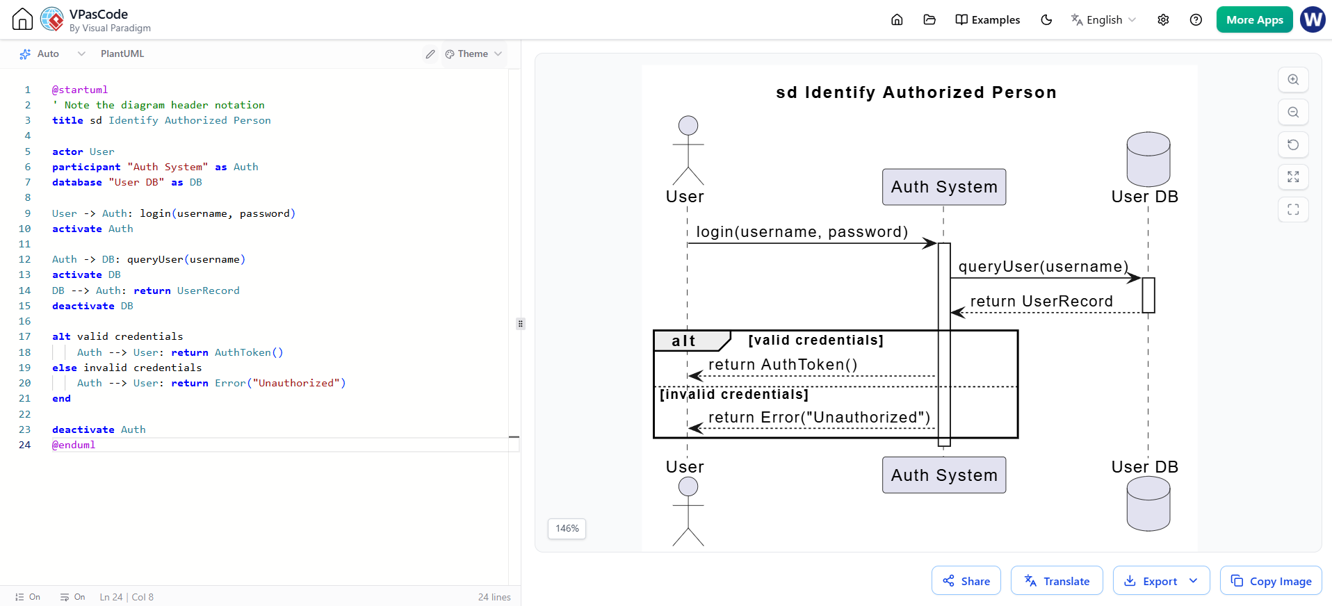
Interaction (Sequence) Diagrams: These emphasize the time sequence of messages exchanged between participants (Lifelines). Time flows strictly from top to bottom, making them perfect for detailing complex API calls or user interactions.
@startuml
left to right direction
actor Customer as c
actor "Payment Gateway" as pg <<system>>

rectangle "E-Commerce System" {
    usecase "Browse Products" as UC1
    usecase "Place Order" as UC2
    usecase "Process Payment" as UC3
}

c --> UC1
c --> UC2
' Include relationship: Placing an order inherently requires processing payment
UC2 ..> UC3 : <<include>>
UC3 --> pg
@enduml
@startuml
' Note the diagram header notation
title sd Identify Authorized Person

actor User
participant "Auth System" as Auth
database "User DB" as DB

User -> Auth: login(username, password)
activate Auth

Auth -> DB: queryUser(username)
activate DB
DB --> Auth: return UserRecord
deactivate DB

alt valid credentials
    Auth --> User: return AuthToken()
else invalid credentials
    Auth --> User: return Error("Unauthorized")
end

deactivate Auth
@enduml
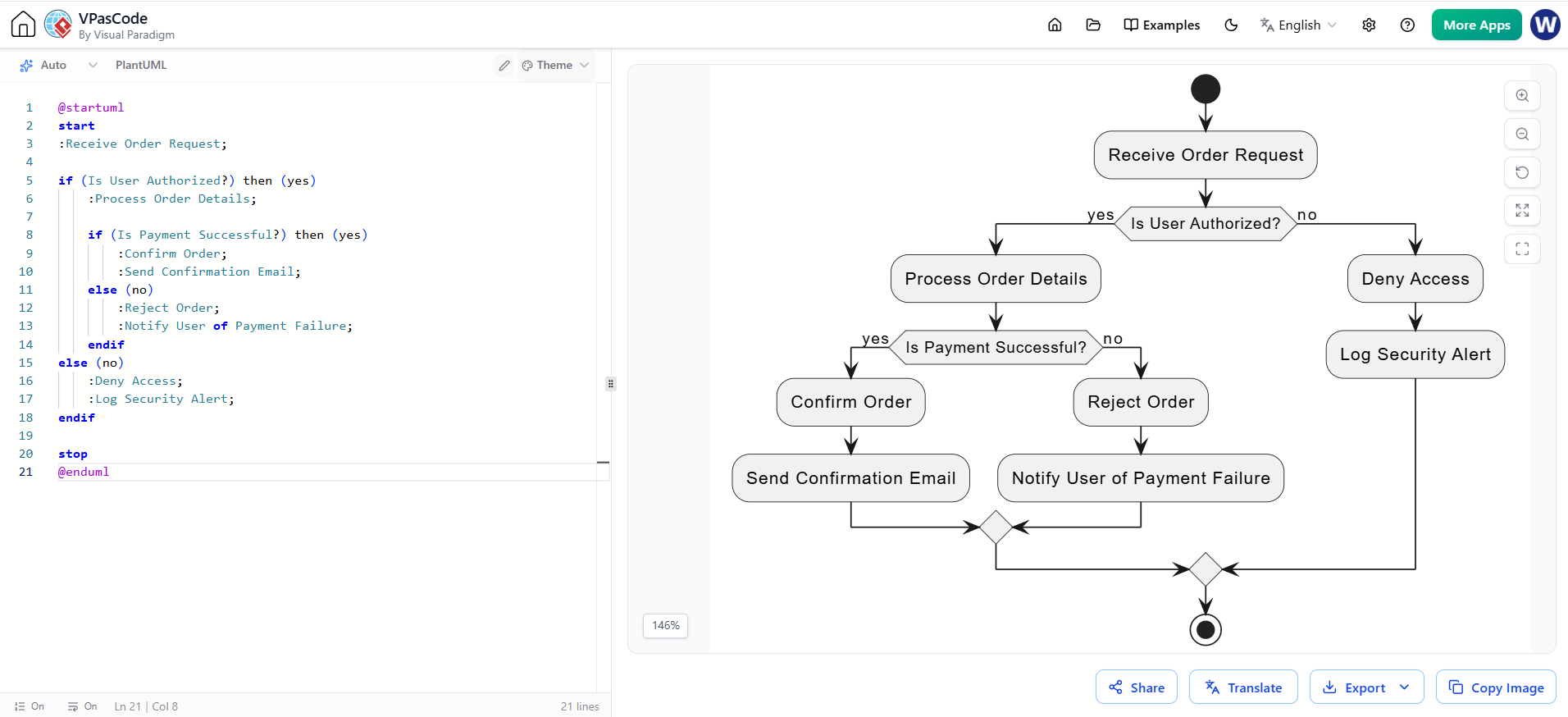
@startuml
start
:Receive Order Request;

if (Is User Authorized?) then (yes)
    :Process Order Details;

    if (Is Payment Successful?) then (yes)
        :Confirm Order;
        :Send Confirmation Email;
    else (no)
        :Reject Order;
        :Notify User of Payment Failure;
    endif
else (no)
    :Deny Access;
    :Log Security Alert;
endif

stop
@enduml
To ensure your diagrams are universally understood, UML 2.0 enforces specific notation rules:
Diagram Headers: Every diagram should ideally have a header in the upper-left corner indicating the diagram type and its specific name. For example, a sequence diagram might be labeled sd Identify Authorized Person (where sd stands for sequence diagram).
Keywords and Stereotypes: UML allows you to extend its basic vocabulary using Stereotypes. These are text strings enclosed in guillemets (e.g., «interface», «actor», «entity») placed above or below the element name to give it a specific, customized meaning.
Visibility Modifiers: When defining attributes and operations inside a class, you must denote their accessibility using specific symbols:
+ Public: Accessible from anywhere.
- Private: Accessible only within the class itself.
# Protected: Accessible within the class and its subclasses (children).
~ Package: Accessible only by other classes within the same package/namespace.
In an era of rapid development and agile methodologies, some might question the need for formal modeling. However, the primary goal of UML is to provide a formal foundation that is simultaneously understandable to humans and parsable by computers.
Universal Communication: It eliminates ambiguity. A well-drawn UML diagram communicates complex architectural decisions faster and more clearly than pages of text.
Blueprint for Development: Just as a civil engineer wouldn't build a bridge without a blueprint, software engineers use UML to map out system boundaries, database schemas, and API interactions before writing a single line of code.
Tooling Integration: Modern IDEs and CASE (Computer-Aided Software Engineering) tools i.e. Visual Paradigm, can read UML models to auto-generate code skeletons, database schemas, and documentation.
UML 2.0 is an incredibly powerful visual language that brings order to the complexity of software engineering and business process design. By dividing concepts into Structural (the static building blocks) and Behavioral (the dynamic interactions), UML allows teams to view a system from multiple necessary perspectives.
While it may seem technical at first glance, mastering the basics of classes, use cases, and sequence diagrams will vastly improve your ability to design, communicate, and document software systems. Remember that UML is a tool to aid your thinking and communication—not a rigid set of rules to be followed blindly. Start small, sketch out your next system's architecture, and let the visual clarity of UML guide your development process.

