
When designing complex software systems, defining the static structure (the "nouns" like classes, components, and databases) is only half the battle. To truly understand how a system functions, software architects and engineers must also model its dynamic behavior (the "verbs"). In the Unified Modeling Language (UML), the dynamic aspects of a system are captured using two primary behavioral building blocks: Interactions and State Machines.
While both are essential for modeling system behavior, they approach the task from fundamentally different perspectives. This comprehensive guide will explore the core concepts, key elements, and visual diagrams of both Interactions and State Machines, providing practical PlantUML examples to illustrate how they bring software designs to life.
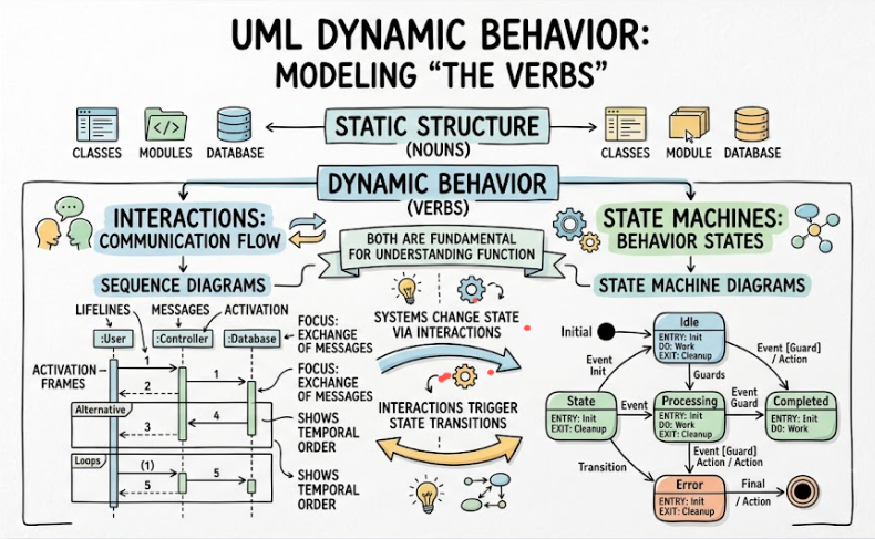
Interactions represent the collaborative nature of software. They model how a "society of objects" work together to achieve a specific goal, acting as the "verbs" of your system's model.
Primary Focus: The flow of control and data from object to object. It emphasizes communication and the coordination required to accomplish a specific purpose (like processing a payment or loading a webpage).
Context of Use: Interactions are typically used to model the flow of control within a specific operation, a class, a component, a use case, or even the entire system. They are perfect for illustrating "scenarios."
Core Elements:
Objects (Roles): The specific instances participating in the scenario.
Links: The semantic connections or communication pathways between the objects.
Messages: The communications exchanged over the links that convey information, request actions, or trigger activity.
Interactions are visualized using Interaction Diagrams. The two most common types are:
Sequence Diagrams: Emphasize the time-ordering of messages. They show exactly when messages are sent and received along a vertical timeline.
Collaboration (Communication) Diagrams: Emphasize the structural organization of the objects. They show who is talking to whom via spatial links, with time indicated by sequence numbers.
Below is an example of a Sequence Diagram modeling the interaction between a Customer, an Order System, and a Payment Gateway during an e-commerce checkout.
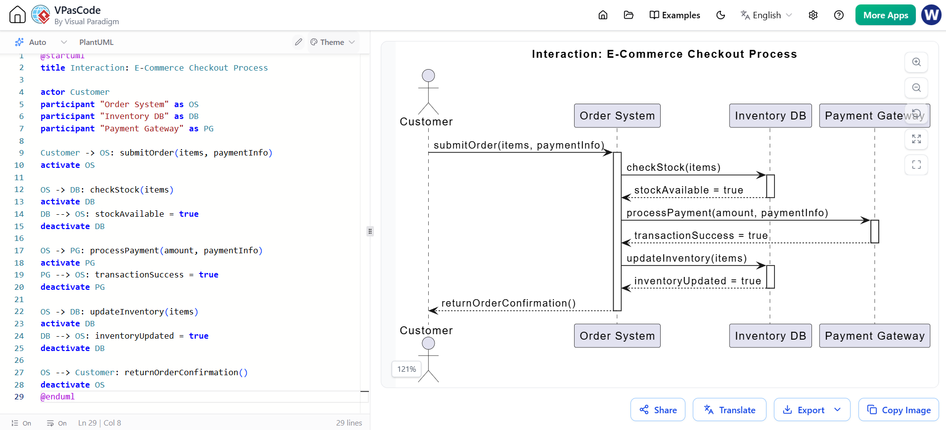
@startuml
title Interaction: E-Commerce Checkout Process

actor Customer
participant "Order System" as OS
participant "Inventory DB" as DB
participant "Payment Gateway" as PG

Customer -> OS: submitOrder(items, paymentInfo)
activate OS

OS -> DB: checkStock(items)
activate DB
DB --> OS: stockAvailable = true
deactivate DB

OS -> PG: processPayment(amount, paymentInfo)
activate PG
PG --> OS: transactionSuccess = true
deactivate PG

OS -> DB: updateInventory(items)
activate DB
DB --> OS: inventoryUpdated = true
deactivate DB

OS --> Customer: returnOrderConfirmation()
deactivate OS
@enduml
While interactions look at the macro-level collaboration of many objects, State Machines zoom in on the micro-level lifecycle of a single object. They specify how an object’s behavior is affected by its past, tracking the sequences of states it goes through in response to various events.
Primary Focus: The flow of control from state to state or activity to activity over the lifetime of a single instance. It emphasizes memory—how past events dictate current and future behavior.
Context of Use: They are most commonly used to model the lifetime of an instance of a class (e.g., an Order or a UserAccount), a use case, or the entire system. They are especially critical for reactive or event-driven systems.
Core Elements:
States: The conditions or situations during an object's life (e.g., "Pending", "Active", "Closed").
Transitions: The movement from one state to another.
Events: The stimuli or triggers that cause a transition to occur (e.g., a button click, a timer expiring, a message received).
Activities/Actions: The computations or tasks that are executed as a result of entering a state or crossing a transition.
State machines are visualized through two main types of diagrams:
Statechart (State Machine) Diagrams: Focus on event-ordered behavior. They map out the distinct states of an object and the events that trigger transitions between them.
Activity Diagrams: Focus on the flow of control from one internal activity to another. They are excellent for modeling complex workflows, business processes, or the internal logic of a single operation.
Here is a Statechart Diagram showing the lifecycle of an Order object, illustrating how it transitions through various states based on specific events.
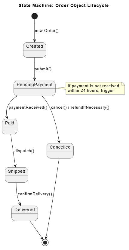
@startuml
title State Machine: Order Object Lifecycle

[*] --> Created : new Order()
Created --> PendingPayment : submit()
PendingPayment --> Paid : paymentReceived()
PendingPayment --> Cancelled : cancel() / refundIfNecessary()
Paid --> Shipped : dispatch()
Shipped --> Delivered : confirmDelivery()
Delivered --> [*]
Cancelled --> [*]

note right of PendingPayment
  If payment is not received
  within 24 hours, trigger
  'timeout' event to Cancelled.
end note
@enduml
Here is an Activity Diagram modeling the internal workflow of processing that same order, highlighting the flow of control and decision points.
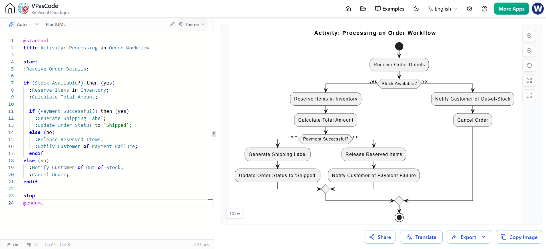
@startuml
title Activity: Processing an Order Workflow

start
:Receive Order Details;

if (Stock Available?) then (yes)
  :Reserve Items in Inventory;
  :Calculate Total Amount;

  if (Payment Successful?) then (yes)
    :Generate Shipping Label;
    :Update Order Status to 'Shipped';
  else (no)
    :Release Reserved Items;
    :Notify Customer of Payment Failure;
  endif
else (no)
  :Notify Customer of Out-of-Stock;
  :Cancel Order;
endif

stop
@enduml
To easily distinguish between these two behavioral building blocks, refer to the comparison table below:
| Feature | Interactions | State Machines |
|---|---|---|
| Primary Focus | Society of objects working together. | Individual object’s lifetime behavior. |
| Flow Emphasis | From object to object. | From state to state or activity to activity. |
| Core Components | Messages, links, and roles. | States, transitions, and events. |
| Main Diagrams | Sequence and Collaboration diagrams. | Statechart and Activity diagrams. |
| Application | Modeling scenarios, use cases, or operations. | Modeling reactive objects, lifecycles, or workflows. |
It is crucial to understand that Interactions and State Machines are not mutually exclusive; rather, they are deeply connected semantically. A robust UML model uses both in tandem to provide a complete picture of system dynamics.
State Machines define the rules: A state machine can be used to specify the legal partial ordering of an interface's operations. For example, the State Machine of an Order dictates that an order must be in the Paid state before it can transition to the Shipped state.
Interactions show the execution: An interaction diagram then shows a specific, real-world sequence of those operations being carried out by objects to satisfy those rules. The Sequence diagram will show the exact messages passed between the PaymentGateway and the OrderSystem to trigger that legal transition.
By combining the macro-view of Interactions with the micro-view of State Machines, developers can ensure that their system not only collaborates effectively but also maintains strict, predictable internal logic.
Mastering the dynamic aspects of UML is essential for designing resilient, well-architected software. Interactions allow us to map out the collaborative symphony of objects, ensuring that data and control flow correctly across system boundaries. Conversely, State Machines allow us to rigorously define the internal lifecycle and reactive logic of individual entities, ensuring they behave predictably in response to events.
By understanding the distinct focuses of these two behavioral building blocks—and knowing how to leverage Sequence, Collaboration, Statechart, and Activity diagrams—software engineers can bridge the gap between abstract requirements and concrete, executable code, ultimately leading to more robust and maintainable software systems.

