
In modern software engineering, the shift from monolithic, waterfall-style development to iterative and incremental development has been a game-changer. However, managing iterations without a clear focal point can lead to fragmented architecture and misaligned business value. This is where the Unified Modeling Language (UML) and, specifically, Use Cases come into play.
In an iterative development process (such as the Rational Unified Process or modern Agile frameworks), use cases are not merely static documentation; they act as the primary drivers of the entire lifecycle. By defining specific units of functionality from the user's perspective, use cases provide a vertical slice of system behavior that guides requirements, analysis, design, implementation, and testing within a single time-boxed iteration.
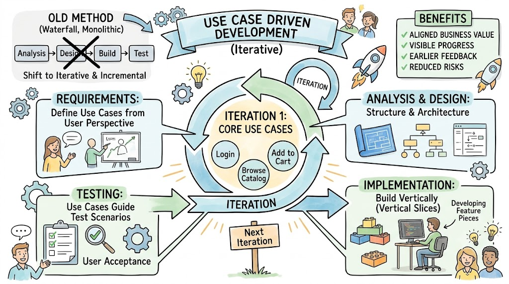
This comprehensive guide explores how use cases drive iterative development within the context of UML modeling. We will break down the core concepts, provide concrete examples, and illustrate the modeling techniques using PlantUML diagrams.
A use-case-driven approach ensures that an iteration is strictly focused on addressing a specific subset of use cases. Instead of attempting to build the entire system architecture at once, the team selects specific behavior sequences to analyze, design, and implement. This creates a "vertical slice" of functionality that results in a working, demonstrable system increment at the end of the time-box.
E-Commerce Platform:
Iteration 1 Scope: "Browse Product Catalog" and "Add Item to Cart". (Focuses on read-heavy operations and basic state management).
Iteration 2 Scope: "Checkout" and "Process Payment". (Focuses on transactional integrity and third-party API integration).
Healthcare Portal:
Iteration 1 Scope: "Patient Registration" and "Schedule Appointment".
Iteration 2 Scope: "Upload Medical Records" and "View Lab Results".
This diagram illustrates how a large system is broken down into scoped iterations using UML packages and notes.
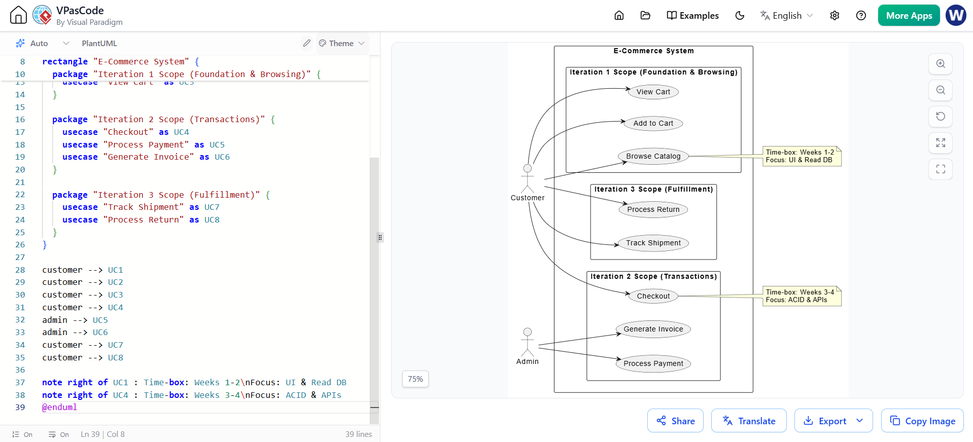
@startuml
left to right direction
skinparam packageStyle rectangle

actor "Customer" as customer
actor "Admin" as admin

rectangle "E-Commerce System" {

  package "Iteration 1 Scope (Foundation & Browsing)" {
    usecase "Browse Catalog" as UC1
    usecase "Add to Cart" as UC2
    usecase "View Cart" as UC3
  }

  package "Iteration 2 Scope (Transactions)" {
    usecase "Checkout" as UC4
    usecase "Process Payment" as UC5
    usecase "Generate Invoice" as UC6
  }

  package "Iteration 3 Scope (Fulfillment)" {
    usecase "Track Shipment" as UC7
    usecase "Process Return" as UC8
  }
}

customer --> UC1
customer --> UC2
customer --> UC3
customer --> UC4
admin --> UC5
admin --> UC6
customer --> UC7
customer --> UC8

note right of UC1 : Time-box: Weeks 1-2\nFocus: UI & Read DB
note right of UC4 : Time-box: Weeks 3-4\nFocus: ACID & APIs
@enduml
Teams do not pick use cases at random for the first iterations. They prioritize architecturally significant use cases to confront risk early. These use cases are selected based on three criteria:
Risk Mitigation: Addressing high business or technical unknowns.
Architectural Impact: Exercising the core structural elements and defining the foundational patterns of the system.
System Stress: Putting pressure on "delicate points" (e.g., performance bottlenecks, concurrency issues) to ensure stability.
Risk Mitigation Example: In a banking app, "Integrate with Legacy Mainframe for Ledger Updates" is prioritized first because if the integration fails, the whole project fails.
Architectural Impact Example: In a streaming service, "Stream Video with Adaptive Bitrate" is prioritized because it forces the team to define the core media server architecture, CDN routing, and client-side buffering logic.
System Stress Example: In a ticketing platform, "Purchase Tickets for a High-Demand Concert" is prioritized early to stress-test the database locking mechanisms and queueing systems under heavy concurrent load.
This sequence diagram models an architecturally significant use case ("Process High-Volume Payment") designed to stress-test the system's concurrency and third-party integration layers.
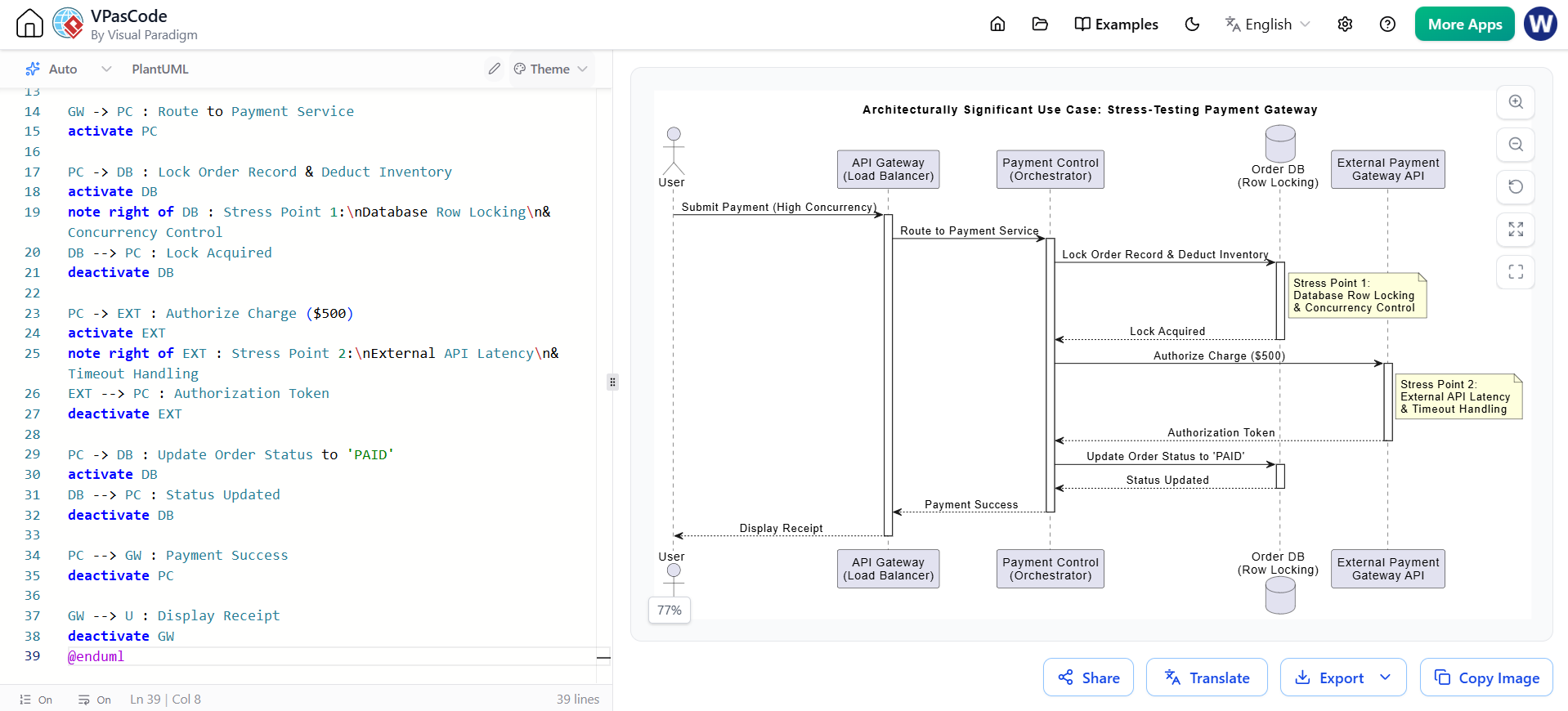
@startuml
skinparam sequenceMessageAlign center
title Architecturally Significant Use Case: Stress-Testing Payment Gateway

actor "User" as U
participant "API Gateway\n(Load Balancer)" as GW
participant "Payment Control\n(Orchestrator)" as PC
database "Order DB\n(Row Locking)" as DB
participant "External Payment\nGateway API" as EXT

U -> GW : Submit Payment (High Concurrency)
activate GW

GW -> PC : Route to Payment Service
activate PC

PC -> DB : Lock Order Record & Deduct Inventory
activate DB
note right of DB : Stress Point 1:\nDatabase Row Locking\n& Concurrency Control
DB --> PC : Lock Acquired
deactivate DB

PC -> EXT : Authorize Charge ($500)
activate EXT
note right of EXT : Stress Point 2:\nExternal API Latency\n& Timeout Handling
EXT --> PC : Authorization Token
deactivate EXT

PC -> DB : Update Order Status to 'PAID'
activate DB
DB --> PC : Status Updated
deactivate DB

PC --> GW : Payment Success
deactivate PC

GW --> U : Display Receipt
deactivate GW
@enduml
As an iteration progresses, the selected use case acts as the blueprint guiding the team through different UML disciplines. In UML Analysis and Design, this is often realized using the Boundary-Control-Entity (BCE) pattern:
Requirements: The Use Case diagram defines the "what".
Analysis & Design: The team identifies logical elements to realize the use case. Boundary classes handle interaction with actors/external systems; Control classes handle orchestration and business logic; Entity classes represent domain data.
Implementation & Validation: Developers write the code for these classes, and QA writes test cases directly mapped to the use case scenarios.
Use Case: "Register New User"
Boundary: RegistrationUI (handles HTTP POST requests and validates input format).
Control: UserRegistrationService (checks if email exists, hashes password, triggers welcome email).
Entity: UserAccount (stores ID, email, hashed password, creation date).
Use Case: "Calculate Shipping Rate"
Boundary: ShippingAPIAdapter (translates external carrier API responses).
Control: ShippingCalculator (applies business rules, e.g., free shipping over $50).
Entity: PackageDimensions, DestinationZip.
This class diagram demonstrates how a single use case is decomposed into Boundary, Control, and Entity classes during the design phase.
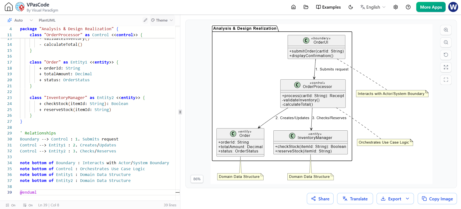
@startuml
skinparam classAttributeIconSize 0

package "Analysis & Design Realization" {

    class "OrderUI" as Boundary <<boundary>> {
        + submitOrder(cartId: String)
        + displayConfirmation()
    }

    class "OrderProcessor" as Control <<control>> {
        + process(cartId: String): Receipt
        - validateInventory()
        - calculateTotal()
    }

    class "Order" as Entity1 <<entity>> {
        + orderId: String
        + totalAmount: Decimal
        + status: OrderStatus
    }

    class "InventoryManager" as Entity2 <<entity>> {
        + checkStock(itemId: String): Boolean
        + reserveStock(itemId: String)
    }
}

' Relationships
Boundary --> Control : 1. Submits request
Control --> Entity1 : 2. Creates/Updates
Control --> Entity2 : 3. Checks/Reserves

note bottom of Boundary : Interacts with Actor/System Boundary
note bottom of Control : Orchestrates Use Case Logic
note bottom of Entity1 : Domain Data Structure
note bottom of Entity2 : Domain Data Structure

@enduml
Each iteration aims to produce a demonstrable result based on the driving use cases. This results in an executable system increment that provides empirical feedback. If a use case proves too complex for the current time-box, it is broken down or re-planned for a future iteration. This ensures stakeholders have clear, honest visibility into the project's genuine status, preventing the "90% done" syndrome common in traditional development.
Feedback Loop Example: During the demo for "Search Products", stakeholders realize the search is too slow. The feedback dictates that the next iteration must prioritize "Implement ElasticSearch Indexing" before adding new features like "Filter by Category".
Re-planning Example: The use case "Generate Complex Financial Report" is estimated to take 3 weeks, but the iteration is only 2 weeks long. The team splits it: Iteration 1 delivers "Generate Basic Summary Report", and Iteration 2 delivers "Add Drill-down Capabilities to Report".
This activity diagram models the lifecycle of an iteration, highlighting how use cases drive the process and how feedback loops back into planning.
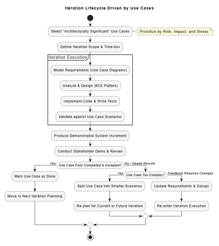
@startuml
skinparam ActivityBackgroundColor #f5f5f5
skinparam ActivityBorderColor #333333

title Iteration Lifecycle Driven by Use Cases

start

:Select "Architecturally Significant" Use Cases;
note right: Prioritize by Risk, Impact, and Stress

:Define Iteration Scope & Time-box;

partition "Iteration Execution" {
    :Model Requirements (Use Case Diagrams);

    :Analyze & Design (BCE Pattern);

    :Implement Code & Write Tests;

    :Validate against Use Case Scenarios;
}

:Produce Demonstrable System Increment;

:Conduct Stakeholder Demo & Review;

if (Use Case Fully Completed & Accepted?) then (Yes)
    :Mark Use Case as Done;
    :Move to Next Iteration Planning;
else (No / Needs Rework)
    if (Use Case Too Complex?) then (Yes)
        :Split Use Case into Smaller Scenarios;
        :Re-plan for Current or Future Iteration;
    else (Feedback Requires Changes)
        :Update Requirements & Design;
        :Re-enter Iteration Execution;
    endif
endif

stop
@enduml
In the realm of UML modeling and iterative software development, use cases are far more than mere requirement gathering tools. They are the fundamental engine that drives the project forward. By defining the scope of iterations, prioritizing architecturally significant risks, guiding the transition from analysis to implementation via patterns like BCE, and facilitating continuous stakeholder feedback, use cases ensure that development remains strictly results-oriented. They guarantee that every sprint or iteration delivers observable, tangible value to the user while systematically de-risking the system's architecture.
To effectively model, manage, and realize these use-case-driven iterations, having robust tooling is essential. We highly recommend Visual Paradigm for your UML modeling needs. Visual Paradigm offers comprehensive support for use-case-driven development, featuring intuitive drag-and-drop diagramming, seamless integration of the Boundary-Control-Entity (BCE) pattern, and powerful code-generation capabilities. Furthermore, its iteration management and model-based testing features ensure that your UML models remain perfectly synchronized with your iterative development lifecycle, bridging the gap between architectural design and executable code.

