
In modern software engineering, particularly within iterative and agile frameworks, not all use cases are created equal. While every use case adds business value, only a select few dictate the structural integrity, technical feasibility, and ultimate success of the system's foundation. These are known as Architecturally Significant Use Cases (ASUCs).
Identifying and modeling ASUCs early in the development lifecycle allows teams to mitigate high risks, validate complex technical integrations, and prove the viability of the proposed architecture before committing to full-scale development.
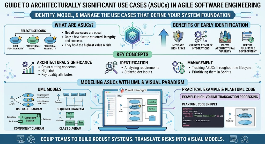
This comprehensive guide explores the concept of ASUCs within the context of UML (Unified Modeling Language). By leveraging Visual Paradigm as our primary modeling tool, we will translate abstract architectural risks into concrete, visual models. Through key concepts, practical examples, and PlantUML diagram code, this guide will equip you with the knowledge to identify, model, and manage the use cases that truly matter.
An Architecturally Significant Use Case is a unit of functionality selected to drive development iterations because it addresses critical uncertainties or demonstrates core structural elements of the system.
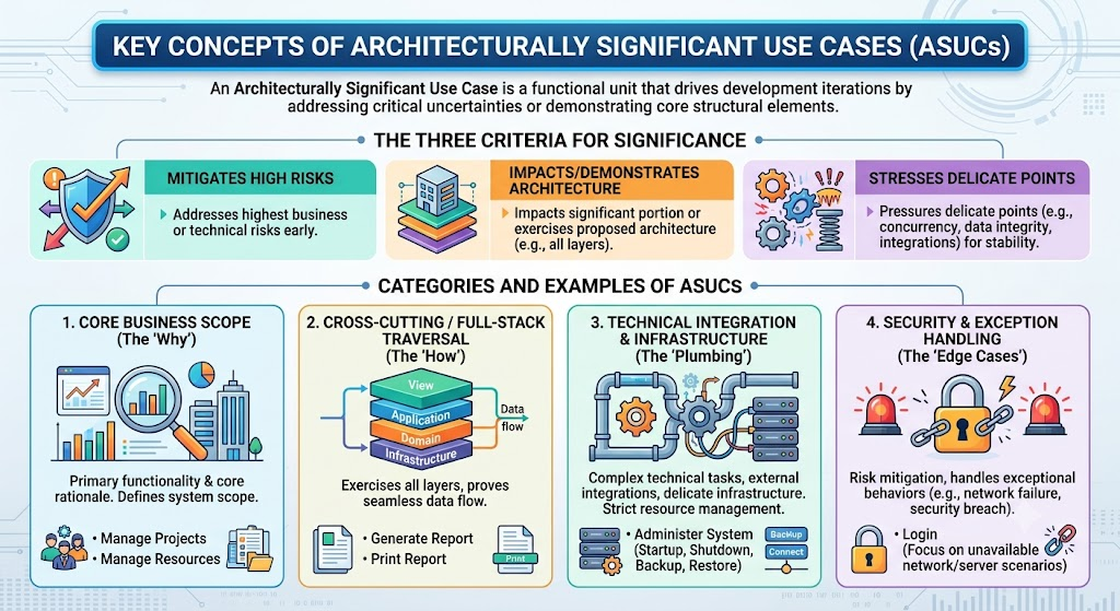
A use case earns the "architecturally significant" designation if it meets one or more of the following criteria:
Mitigates High Risks: It addresses the highest business or technical risks early in the project.
Impacts/Demonstrates Architecture: It impacts a significant portion of the system's architecture or exercises the proposed architectural approach (e.g., traversing all architectural layers).
Stresses Delicate Points: It puts pressure on the "delicate points" of the system (e.g., concurrency, data integrity, external integrations) to ensure stability.
Based on industry standards and architectural analysis, ASUCs generally fall into several distinct categories:
These use cases represent the primary functionality and the core business rationale for the system. They are used to define the system's scope during the inception phase.
Examples: Manage Projects and Manage Resources in a Project Management System.
These use cases are significant because they exercise all layers of a standard architecture (such as a Four-Layer Architecture: View, Application, Domain, and Infrastructure). They prove that data can flow seamlessly from the user interface down to the database and back.
Examples: Print Report or Generate Report.
These use cases involve complex technical tasks, external system integrations, or delicate infrastructure setups. They are often support or secondary maintenance functions, but they "stress" the architecture by requiring strict resource management.
Examples: Startup, Shutdown, Backup, and Restore (often grouped under Administer System). Connect (establishing connections to external resources).
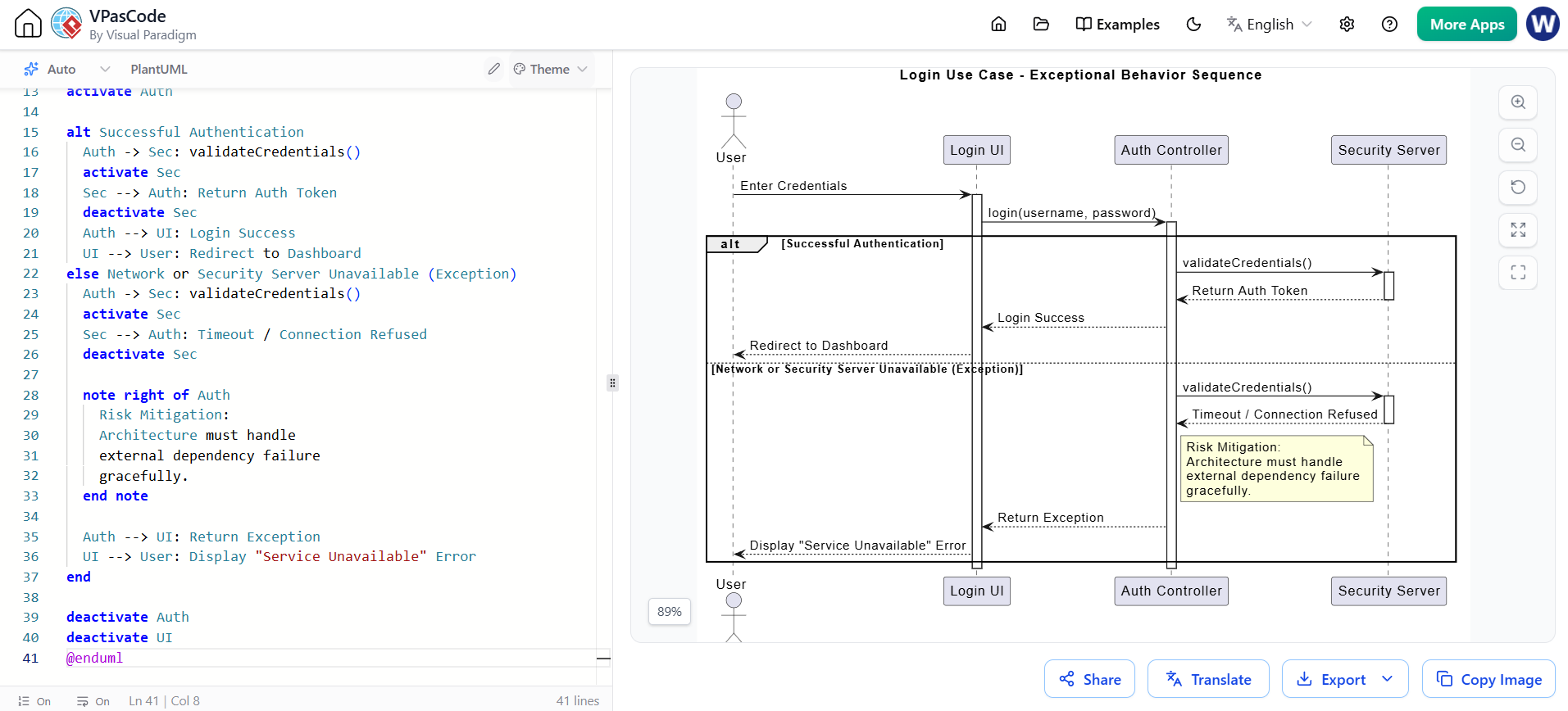
These use cases highlight risk mitigation by forcing the architecture to handle exceptional behavior sequences, such as network failures or security breaches.
Examples: Login (specifically focusing on scenarios where the network or security server is unavailable).
Visual Paradigm is a powerful enterprise modeling tool that provides robust features for managing complex UML diagrams. When modeling ASUCs, Visual Paradigm's traceability and model management features are invaluable.
Use the Model Explorer: Tag your ASUCs with specific stereotypes (e.g., <<architecturally significant>>) in the Model Explorer. This allows you to filter and generate reports specifically for these critical use cases.
Leverage Traceability Matrices: Link your Use Case Diagrams directly to Sequence and Class diagrams. This ensures that every ASUC is backed by detailed behavioral and structural models.
Diagram Navigator: Use the Diagram Navigator to quickly switch between the high-level Use Case scope and the low-level Sequence/Class details of a specific ASUC.
Code Engineering: Utilize Visual Paradigm’s forward engineering to generate skeleton code (e.g., Java, C#) directly from your Class and Sequence diagrams for the ASUCs, ensuring the architecture is implemented exactly as designed.
Below are PlantUML examples demonstrating how to model the ASUCs discussed. You can render these using any PlantUML plugin or online editor, and they can be easily recreated in Visual Paradigm using its intuitive drag-and-drop interface.
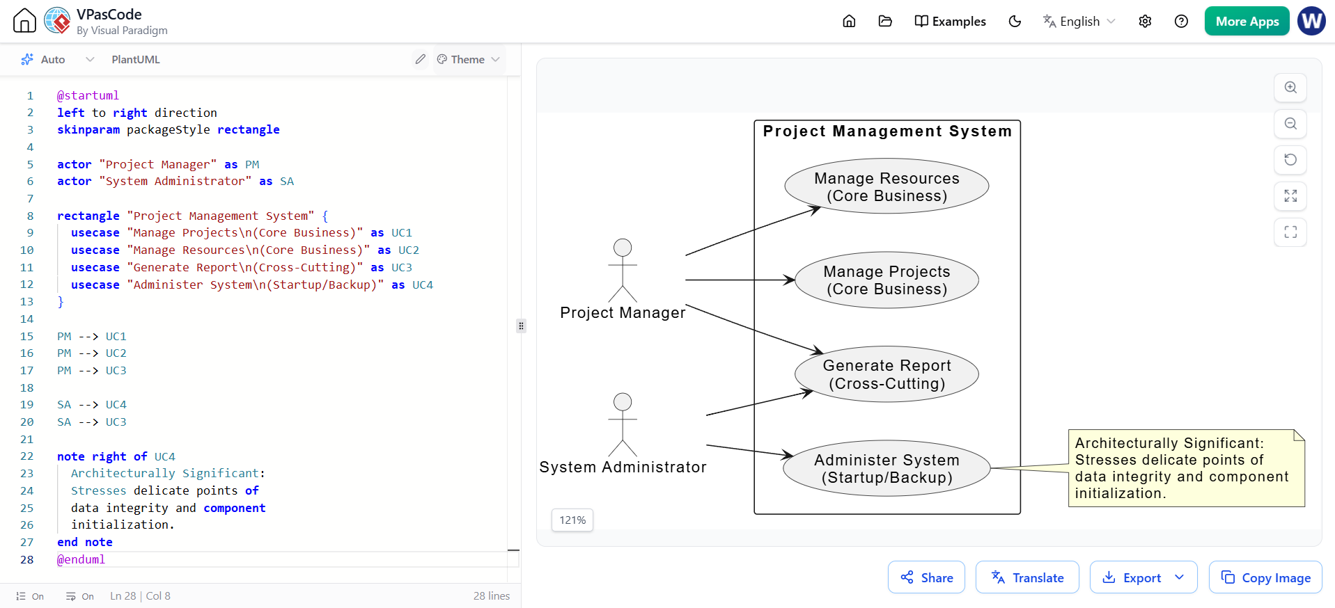
This diagram illustrates the scope of the system, highlighting both the core business ASUCs (Manage Projects) and the infrastructure ASUCs (Administer System).
@startuml
left to right direction
skinparam packageStyle rectangle

actor "Project Manager" as PM
actor "System Administrator" as SA

rectangle "Project Management System" {
  usecase "Manage Projects\n(Core Business)" as UC1
  usecase "Manage Resources\n(Core Business)" as UC2
  usecase "Generate Report\n(Cross-Cutting)" as UC3
  usecase "Administer System\n(Startup/Backup)" as UC4
}

PM --> UC1
PM --> UC2
PM --> UC3

SA --> UC4
SA --> UC3

note right of UC4
  Architecturally Significant:
  Stresses delicate points of
  data integrity and component
  initialization.
end note
@enduml
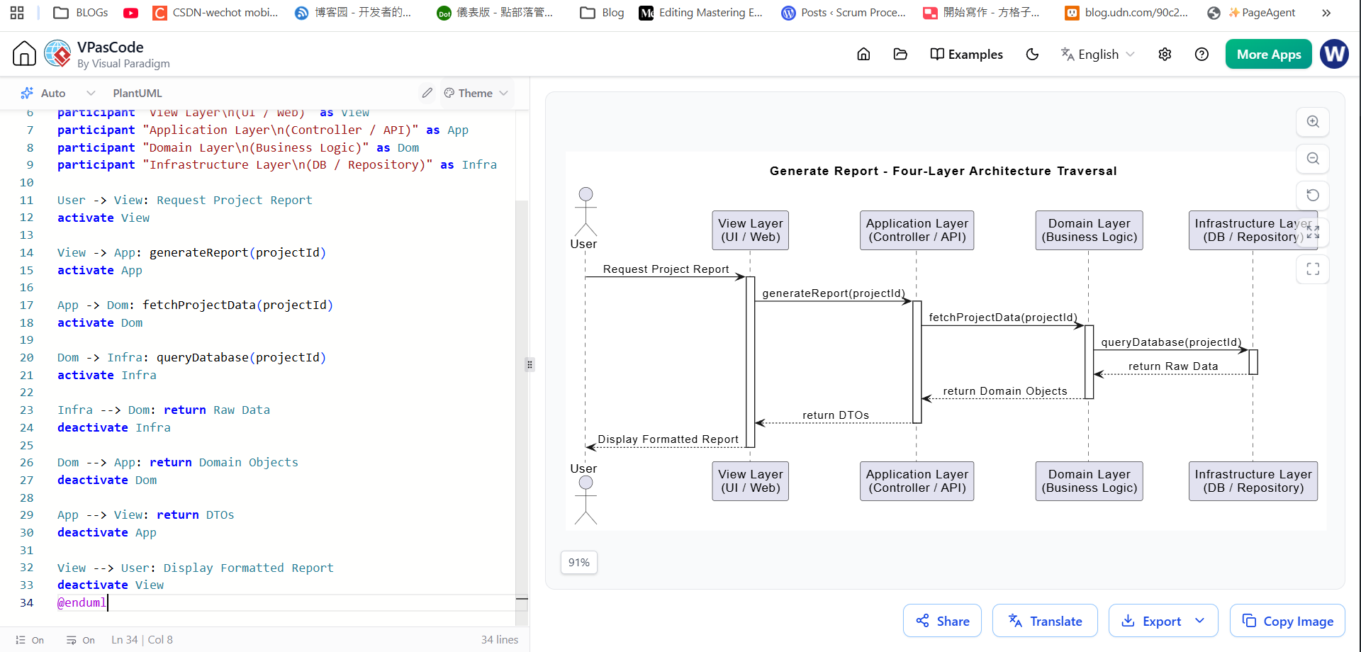
The Generate Report use case is a classic ASUC because it forces the design to demonstrate the Four-Layer Architecture. This sequence diagram shows the request traversing from the View down to the Infrastructure layer.
@startuml
skinparam sequenceMessageAlign center
title Generate Report - Four-Layer Architecture Traversal

actor User
participant "View Layer\n(UI / Web)" as View
participant "Application Layer\n(Controller / API)" as App
participant "Domain Layer\n(Business Logic)" as Dom
participant "Infrastructure Layer\n(DB / Repository)" as Infra

User -> View: Request Project Report
activate View

View -> App: generateReport(projectId)
activate App

App -> Dom: fetchProjectData(projectId)
activate Dom

Dom -> Infra: queryDatabase(projectId)
activate Infra

Infra --> Dom: return Raw Data
deactivate Infra

Dom --> App: return Domain Objects
deactivate Dom

App --> View: return DTOs
deactivate App

View --> User: Display Formatted Report
deactivate View
@enduml
The Login use case is architecturally significant when modeling exceptional flows. This diagram demonstrates how the system handles a critical technical risk: the unavailability of the security server.
@startuml
title Login Use Case - Exceptional Behavior Sequence

actor User
participant "Login UI" as UI
participant "Auth Controller" as Auth
participant "Security Server" as Sec

User -> UI: Enter Credentials
activate UI

UI -> Auth: login(username, password)
activate Auth

alt Successful Authentication
  Auth -> Sec: validateCredentials()
  activate Sec
  Sec --> Auth: Return Auth Token
  deactivate Sec
  Auth --> UI: Login Success
  UI --> User: Redirect to Dashboard
else Network or Security Server Unavailable (Exception)
  Auth -> Sec: validateCredentials()
  activate Sec
  Sec --> Auth: Timeout / Connection Refused
  deactivate Sec

  note right of Auth
    Risk Mitigation:
    Architecture must handle
    external dependency failure
    gracefully.
  end note

  Auth --> UI: Return Exception
  UI --> User: Display "Service Unavailable" Error
end

deactivate Auth
deactivate UI
@enduml
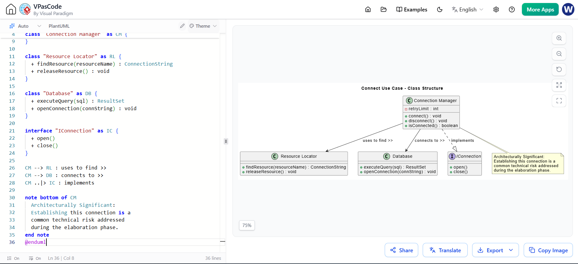
The Connect use case addresses the technical risk of establishing external connections. This class diagram models the Connection Manager and its interactions with the Resource Locator and the Database.
@startuml
title Connect Use Case - Class Structure

class "Connection Manager" as CM {
  + connect() : void
  + disconnect() : void
  + isConnected() : boolean
  - retryLimit : int
}

class "Resource Locator" as RL {
  + findResource(resourceName) : ConnectionString
  + releaseResource() : void
}

class "Database" as DB {
  + executeQuery(sql) : ResultSet
  + openConnection(connString) : void
}

interface "IConnection" as IC {
  + open()
  + close()
}

CM --> RL : uses to find >>
CM --> DB : connects to >>
CM ..|> IC : implements

note bottom of CM
  Architecturally Significant:
  Establishing this connection is a
  common technical risk addressed
  during the elaboration phase.
end note
@enduml
Identifying and modeling Architecturally Significant Use Cases is not just an academic exercise; it is a critical risk-management strategy. By focusing on use cases that mitigate high risks, traverse all architectural layers, and stress delicate system points, development teams can validate their technical approach before writing production code.
Through the lens of UML, we can transform these abstract concepts into tangible blueprints. As demonstrated, Visual Paradigm provides the robust tooling necessary to map out the scope of core business functions, trace the four-layer traversal of a reporting feature, model the exceptional flows of a login sequence, and define the class structures required for complex technical integrations.
By prioritizing ASUCs in your modeling phase, you ensure that your software architecture is not only theoretically sound but practically resilient, paving the way for a successful and stable software delivery.

