
In Unified Modeling Language (UML) use case modeling, understanding the role of actors is fundamental to capturing system requirements accurately. While many practitioners initially think of actors solely as human users, the UML specification explicitly recognizes that external systems can serve as primary actors. This recognition is crucial in today's interconnected software landscape, where systems frequently communicate with other systems, APIs, databases, and automated services.
This guide explores the concept of external systems as primary actors in UML use case diagrams, providing clear definitions, practical examples, and visual representations using PlantUML. Whether you're modeling an e-commerce platform that integrates with payment gateways, a logistics system that communicates with shipping providers, or an enterprise application that syncs with external databases, understanding how to properly represent external systems as actors is essential for accurate requirements capture and system design.
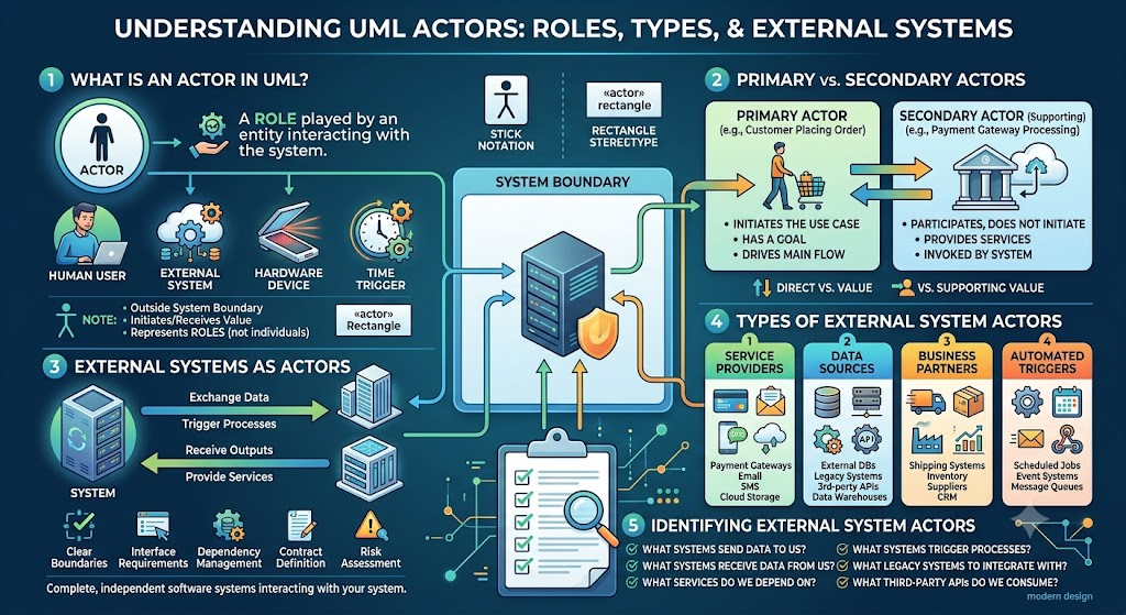
An actor in UML represents a role played by an entity that interacts with the system. According to UML specifications, an actor can be:
A human user (e.g., Customer, Administrator, Accountant)
An external system (e.g., Payment Gateway, Shipping System, Legacy Database)
A hardware device (e.g., Scanner, Printer, Sensor)
A time trigger (e.g., Scheduled Job, Timer)
Key Characteristics:
Actors reside outside the system boundary
Actors initiate interactions or receive value from the system
Actors represent roles, not specific individuals or instances
Actors are depicted using stick figure notation (for humans) or rectangle with «actor» stereotype (for systems)
Understanding the distinction between primary and secondary actors is crucial for proper use case modeling:
Primary Actor:
Initiates the use case
Has a goal that the use case fulfills
Drives the main flow of events
Receives direct value from the use case execution
Example: A Customer placing an order
Secondary Actor (Supporting Actor):
Participates in the use case but does not initiate it
Provides services or information to the system
Is invoked by the system during use case execution
Example: A Payment Gateway that processes payments when the system requests it
Important Note: An external system can be either a primary or secondary actor depending on the specific use case context.
External systems are complete, independent software systems that interact with your system. They are modeled as actors when they:
Exchange data with your system
Trigger processes in your system
Receive outputs from your system
Provide services that your system consumes
Why Model External Systems as Actors?
Clear Boundaries: Defines what is inside vs. outside your system
Interface Requirements: Identifies integration points and APIs needed
Dependency Management: Highlights external dependencies
Contract Definition: Establishes clear interaction protocols
Risk Assessment: Identifies potential points of failure
External systems can be categorized based on their interaction patterns:
A. Service Providers:
Payment Gateways (Stripe, PayPal)
Email Services (SendGrid, Amazon SES)
SMS Services (Twilio)
Cloud Storage (AWS S3, Google Cloud Storage)
B. Data Sources:
External Databases
Legacy Systems
Third-party APIs (Weather Data, Stock Prices)
Data Warehouses
C. Business Partners:
Shipping Systems (FedEx, UPS, DHL)
Inventory Management Systems
Supplier Systems
Customer Relationship Management (CRM) Systems
D. Automated Triggers:
Scheduled Batch Jobs
Event-Driven Systems
Message Queues (RabbitMQ, Kafka)
Webhook Senders
Use these questions to identify external system actors:
What systems send data to our system?
What systems receive data from our system?
What external services does our system depend on?
What systems trigger automated processes in our system?
What legacy systems must we integrate with?
What third-party APIs do we consume?
Scenario: An online store processes customer orders and integrates with multiple external systems.
Actors:
Primary Actors:
Customer (human) - Places orders
Payment Gateway (external system) - Initiates payment confirmation webhooks
Shipping System (external system) - Requests order fulfillment data
Secondary Actors:
Payment Gateway (external system) - Processes payment requests
Inventory System (external system) - Provides stock levels
Email Service (external system) - Sends notifications
Use Cases:
Place Order (Primary: Customer)
Process Payment (Primary: System, Secondary: Payment Gateway)
Confirm Payment (Primary: Payment Gateway)
Ship Order (Primary: System, Secondary: Shipping System)
Update Inventory (Primary: System, Secondary: Inventory System)
Scenario: A hospital system integrates with insurance providers and laboratory systems.
Actors:
Primary Actors:
Doctor (human)
Insurance Provider System (external system) - Submits claim decisions
Laboratory Information System (external system) - Sends test results
Secondary Actors:
Insurance Provider System (external system) - Receives claim submissions
Pharmacy System (external system) - Receives prescriptions
Appointment Scheduling System (external system) - Manages appointments
Use Cases:
Submit Insurance Claim (Primary: System, Secondary: Insurance Provider)
Receive Claim Decision (Primary: Insurance Provider)
Request Lab Test (Primary: Doctor, Secondary: Laboratory System)
Receive Lab Results (Primary: Laboratory System)
Send Prescription (Primary: System, Secondary: Pharmacy System)
Scenario: A banking system processes transactions and communicates with external financial networks.
Actors:
Primary Actors:
Bank Teller (human)
ATM Network (external system) - Initiates withdrawal requests
Payment Switch (external system) - Routes interbank transfers
Secondary Actors:
Credit Bureau (external system) - Provides credit scores
Fraud Detection System (external system) - Validates transactions
Regulatory Reporting System (external system) - Receives compliance data
Use Cases:
Process Withdrawal (Primary: ATM Network)
Transfer Funds (Primary: Payment Switch)
Check Credit Score (Primary: System, Secondary: Credit Bureau)
Validate Transaction (Primary: System, Secondary: Fraud Detection System)
Generate Compliance Report (Primary: System, Secondary: Regulatory Reporting System)
Scenario: A smart home hub integrates with various device manufacturers and cloud services.
Actors:
Primary Actors:
Homeowner (human)
Weather Service API (external system) - Sends weather alerts
Energy Provider System (external system) - Sends pricing updates
Secondary Actors:
Device Manufacturer Cloud (external system) - Receives device commands
Voice Assistant Platform (external system) - Receives status updates
Security Monitoring Service (external system) - Receives alarm triggers
Use Cases:
Adjust Thermostat (Primary: Homeowner)
Receive Weather Alert (Primary: Weather Service API)
Update Energy Pricing (Primary: Energy Provider System)
Control Smart Device (Primary: System, Secondary: Device Manufacturer Cloud)
Trigger Security Alert (Primary: System, Secondary: Security Monitoring Service)
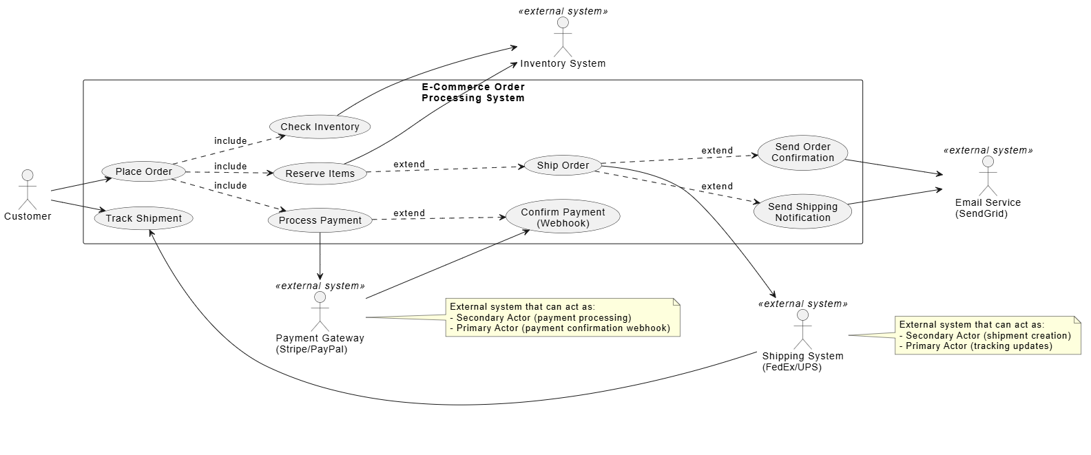
@startuml E-Commerce System Use Case Diagram
left to right direction
skinparam packageStyle rectangle

actor "Customer" as Customer
actor "Payment Gateway\n(Stripe/PayPal)" as PaymentGateway <<external system>>
actor "Shipping System\n(FedEx/UPS)" as ShippingSystem <<external system>>
actor "Inventory System" as InventorySystem <<external system>>
actor "Email Service\n(SendGrid)" as EmailService <<external system>>

rectangle "E-Commerce Order\nProcessing System" {
  usecase "Place Order" as UC1
  usecase "Process Payment" as UC2
  usecase "Confirm Payment\n(Webhook)" as UC3
  usecase "Check Inventory" as UC4
  usecase "Reserve Items" as UC5
  usecase "Ship Order" as UC6
  usecase "Track Shipment" as UC7
  usecase "Send Order\nConfirmation" as UC8
  usecase "Send Shipping\nNotification" as UC9
}

Customer --> UC1
Customer --> UC7

PaymentGateway --> UC3
UC2 --> PaymentGateway

ShippingSystem --> UC7
UC6 --> ShippingSystem

UC4 --> InventorySystem
UC5 --> InventorySystem

UC8 --> EmailService
UC9 --> EmailService

UC1 ..> UC2 : include
UC1 ..> UC4 : include
UC1 ..> UC5 : include
UC2 ..> UC3 : extend
UC5 ..> UC6 : extend
UC6 ..> UC8 : extend
UC6 ..> UC9 : extend

note right of PaymentGateway
  External system that can act as:
  - Secondary Actor (payment processing)
  - Primary Actor (payment confirmation webhook)
end note

note right of ShippingSystem
  External system that can act as:
  - Secondary Actor (shipment creation)
  - Primary Actor (tracking updates)
end note

@enduml
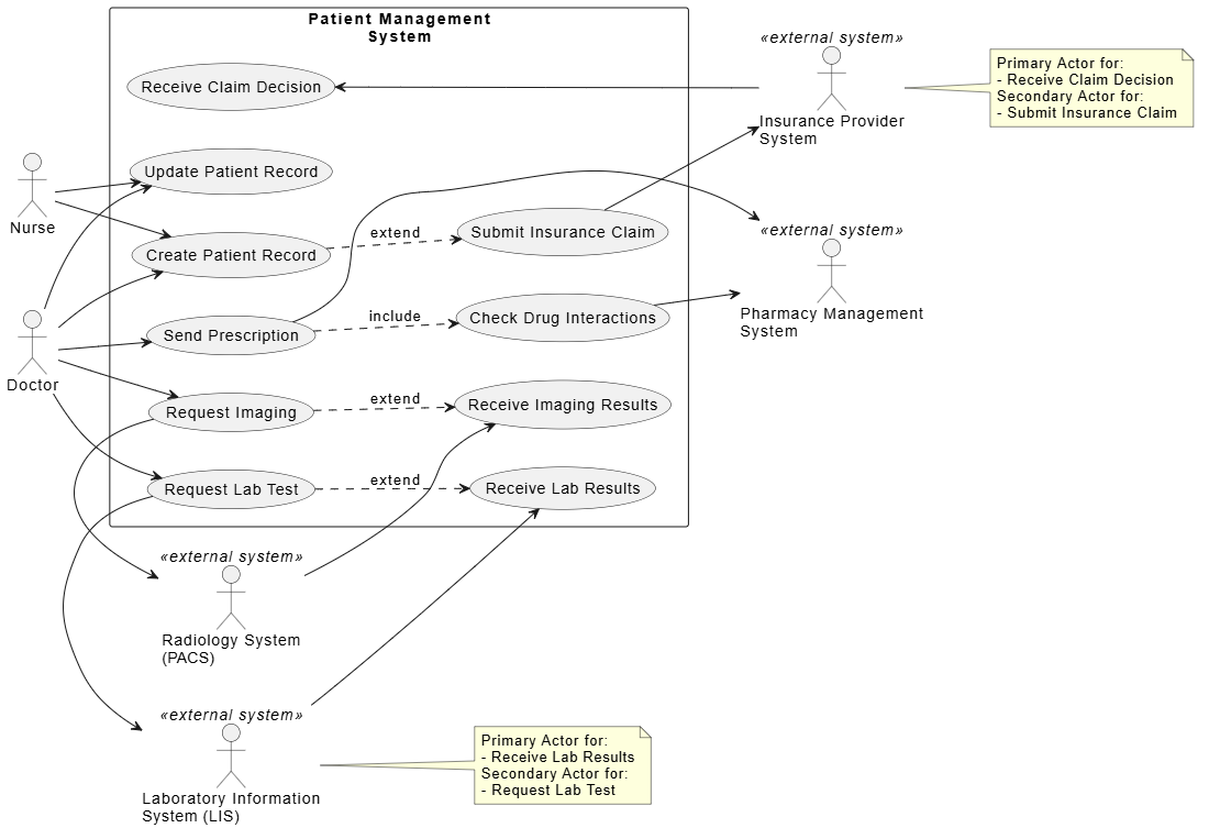
@startuml Healthcare System Use Case Diagram
left to right direction
skinparam packageStyle rectangle

actor "Doctor" as Doctor
actor "Nurse" as Nurse
actor "Insurance Provider\nSystem" as InsuranceProvider <<external system>>
actor "Laboratory Information\nSystem (LIS)" as LIS <<external system>>
actor "Pharmacy Management\nSystem" as Pharmacy <<external system>>
actor "Radiology System\n(PACS)" as PACS <<external system>>

rectangle "Patient Management\nSystem" {
  usecase "Create Patient Record" as UC1
  usecase "Submit Insurance Claim" as UC2
  usecase "Receive Claim Decision" as UC3
  usecase "Request Lab Test" as UC4
  usecase "Receive Lab Results" as UC5
  usecase "Request Imaging" as UC6
  usecase "Receive Imaging Results" as UC7
  usecase "Send Prescription" as UC8
  usecase "Check Drug Interactions" as UC9
  usecase "Update Patient Record" as UC10
}

Doctor --> UC1
Doctor --> UC4
Doctor --> UC6
Doctor --> UC8
Doctor --> UC10

Nurse --> UC1
Nurse --> UC10

InsuranceProvider --> UC3
UC2 --> InsuranceProvider

LIS --> UC5
UC4 --> LIS

PACS --> UC7
UC6 --> PACS

UC8 --> Pharmacy
UC9 --> Pharmacy

UC1 ..> UC2 : extend
UC4 ..> UC5 : extend
UC6 ..> UC7 : extend
UC8 ..> UC9 : include

note right of InsuranceProvider
  Primary Actor for:
  - Receive Claim Decision
  Secondary Actor for:
  - Submit Insurance Claim
end note

note right of LIS
  Primary Actor for:
  - Receive Lab Results
  Secondary Actor for:
  - Request Lab Test
end note

@enduml
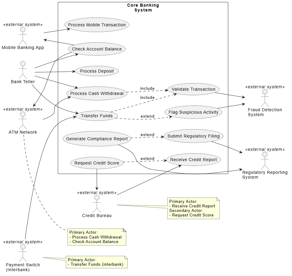
@startuml Banking System Use Case Diagram
left to right direction
skinparam packageStyle rectangle

actor "Bank Teller" as Teller
actor "ATM Network" as ATM <<external system>>
actor "Payment Switch\n(Interbank)" as PaymentSwitch <<external system>>
actor "Credit Bureau" as CreditBureau <<external system>>
actor "Fraud Detection\nSystem" as FraudSystem <<external system>>
actor "Regulatory Reporting\nSystem" as Regulatory <<external system>>
actor "Mobile Banking App" as MobileApp <<external system>>

rectangle "Core Banking\nSystem" {
  usecase "Process Cash Withdrawal" as UC1
  usecase "Process Deposit" as UC2
  usecase "Transfer Funds" as UC3
  usecase "Check Account Balance" as UC4
  usecase "Validate Transaction" as UC5
  usecase "Request Credit Score" as UC6
  usecase "Receive Credit Report" as UC7
  usecase "Flag Suspicious Activity" as UC8
  usecase "Generate Compliance Report" as UC9
  usecase "Submit Regulatory Filing" as UC10
  usecase "Process Mobile Transaction" as UC11
}

Teller --> UC1
Teller --> UC2
Teller --> UC3
Teller --> UC4

ATM --> UC1
UC4 --> ATM

PaymentSwitch --> UC3

CreditBureau --> UC7
UC6 --> CreditBureau

UC5 --> FraudSystem
UC8 --> FraudSystem

UC9 --> Regulatory
UC10 --> Regulatory

MobileApp --> UC11
UC4 --> MobileApp

UC1 ..> UC5 : include
UC3 ..> UC5 : include
UC3 ..> UC8 : extend
UC6 ..> UC7 : extend
UC9 ..> UC10 : extend

note right of ATM
  Primary Actor:
  - Process Cash Withdrawal
  - Check Account Balance
end note

note right of PaymentSwitch
  Primary Actor:
  - Transfer Funds (interbank)
end note

note right of CreditBureau
  Primary Actor:
  - Receive Credit Report
  Secondary Actor:
  - Request Credit Score
end note

@enduml
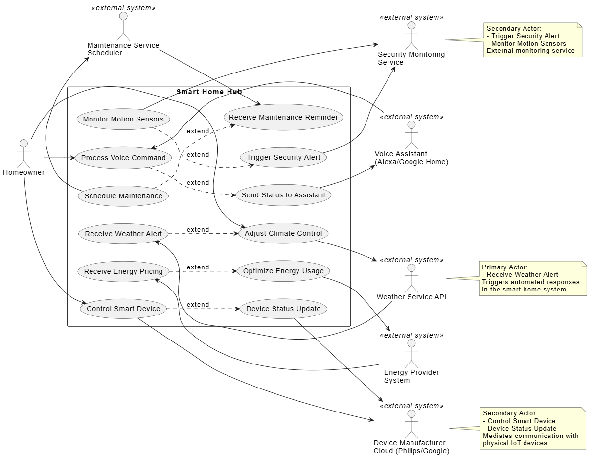
@startuml IoT Smart Home System Use Case Diagram
left to right direction
skinparam packageStyle rectangle

actor "Homeowner" as Homeowner
actor "Weather Service API" as WeatherAPI <<external system>>
actor "Energy Provider\nSystem" as EnergyProvider <<external system>>
actor "Device Manufacturer\nCloud (Philips/Google)" as DeviceCloud <<external system>>
actor "Voice Assistant\n(Alexa/Google Home)" as VoiceAssistant <<external system>>
actor "Security Monitoring\nService" as SecurityService <<external system>>
actor "Maintenance Service\nScheduler" as Maintenance <<external system>>

rectangle "Smart Home Hub" {
  usecase "Receive Weather Alert" as UC1
  usecase "Adjust Climate Control" as UC2
  usecase "Receive Energy Pricing" as UC3
  usecase "Optimize Energy Usage" as UC4
  usecase "Control Smart Device" as UC5
  usecase "Device Status Update" as UC6
  usecase "Process Voice Command" as UC7
  usecase "Send Status to Assistant" as UC8
  usecase "Trigger Security Alert" as UC9
  usecase "Monitor Motion Sensors" as UC10
  usecase "Schedule Maintenance" as UC11
  usecase "Receive Maintenance Reminder" as UC12
}

Homeowner --> UC2
Homeowner --> UC5
Homeowner --> UC7

WeatherAPI --> UC1
UC2 --> WeatherAPI

EnergyProvider --> UC3
UC4 --> EnergyProvider

UC5 --> DeviceCloud
UC6 --> DeviceCloud

VoiceAssistant --> UC7
UC8 --> VoiceAssistant

UC9 --> SecurityService
UC10 --> SecurityService

Maintenance --> UC12
UC11 --> Maintenance

UC1 ..> UC2 : extend
UC3 ..> UC4 : extend
UC5 ..> UC6 : extend
UC7 ..> UC8 : extend
UC10 ..> UC9 : extend
UC11 ..> UC12 : extend

note right of WeatherAPI
  Primary Actor:
  - Receive Weather Alert
  Triggers automated responses
  in the smart home system
end note

note right of DeviceCloud
  Secondary Actor:
  - Control Smart Device
  - Device Status Update
  Mediates communication with
  physical IoT devices
end note

note right of SecurityService
  Secondary Actor:
  - Trigger Security Alert
  - Monitor Motion Sensors
  External monitoring service
end note

@enduml
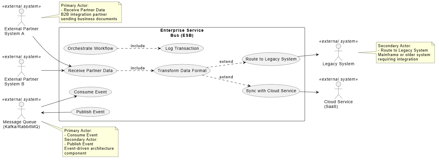
@startuml Enterprise Integration Pattern
left to right direction
skinparam packageStyle rectangle

actor "External Partner\nSystem A" as PartnerA <<external system>>
actor "External Partner\nSystem B" as PartnerB <<external system>>
actor "Legacy System" as Legacy <<external system>>
actor "Cloud Service\n(SaaS)" as CloudService <<external system>>
actor "Message Queue\n(Kafka/RabbitMQ)" as MessageQueue <<external system>>

rectangle "Enterprise Service\nBus (ESB)" {
  usecase "Receive Partner Data" as UC1
  usecase "Transform Data Format" as UC2
  usecase "Route to Legacy System" as UC3
  usecase "Sync with Cloud Service" as UC4
  usecase "Publish Event" as UC5
  usecase "Consume Event" as UC6
  usecase "Orchestrate Workflow" as UC7
  usecase "Log Transaction" as UC8
}

PartnerA --> UC1
PartnerB --> UC1

UC3 --> Legacy
UC4 --> CloudService

UC5 --> MessageQueue
MessageQueue --> UC6

UC1 ..> UC2 : include
UC2 ..> UC3 : extend
UC2 ..> UC4 : extend
UC7 ..> UC8 : include

note right of PartnerA
  Primary Actor:
  - Receive Partner Data
  B2B integration partner
  sending business documents
end note

note right of Legacy
  Secondary Actor:
  - Route to Legacy System
  Mainframe or older system
  requiring integration
end note

note right of MessageQueue
  Primary Actor:
  - Consume Event
  Secondary Actor:
  - Publish Event
  Event-driven architecture
  component
end note

@enduml
Use descriptive names that indicate the system's purpose
Include the actual system name when relevant (e.g., "Payment Gateway (Stripe)")
Add the «external system» stereotype for clarity
Document when an external system plays both roles
Create separate use cases for each interaction direction
Use notes to clarify the dual nature if needed
Specify the communication protocol (REST API, SOAP, Message Queue, etc.)
Document data formats (JSON, XML, EDI, etc.)
Note authentication and security requirements
Model exception flows for external system failures
Include timeout and retry mechanisms
Consider circuit breaker patterns
Note SLA (Service Level Agreement) requirements
Identify fallback systems or manual processes
Document version dependencies
Don't model internal components of external systems
Focus on the interaction interface, not implementation
Keep the external system as a black box
Clearly define what is inside vs. outside your system
Avoid modeling shared databases as actors (they're typically part of the system)
Distinguish between external systems and internal subsystems
Confusing External Systems with Internal Components
✗ Wrong: Modeling your own microservices as actors
✓ Right: Only modeling truly external, independent systems
Overlooking Bidirectional Interactions
✗ Wrong: Only showing one direction of data flow
✓ Right: Creating separate use cases for each interaction direction
Treating Databases as Actors
✗ Wrong: Modeling your database as an external actor
✓ Right: Only modeling external databases owned by other organizations
Ignoring Failure Scenarios
✗ Wrong: Only modeling the "happy path"
✓ Right: Including error handling and timeout use cases
Vague Actor Names
✗ Wrong: "External System"
✓ Right: "Payment Gateway (PayPal)" or "Shipping System (FedEx API)"
Modeling external systems as primary actors in UML use case diagrams is not only valid but essential for accurately representing modern software architectures. As systems become increasingly interconnected through APIs, microservices, and cloud integrations, the ability to properly identify and model external system actors becomes a critical skill for software architects and business analysts.
By recognizing that external systems can initiate use cases, drive business processes, and deliver value just as human actors do, you create more accurate, complete, and useful models. These models serve as better communication tools between technical and business stakeholders, help identify integration requirements early in the development process, and provide a clear roadmap for implementing system interfaces.
Remember that an external system's role—whether primary or secondary—depends on the specific use case context. The same external system might be a primary actor in one scenario (e.g., a Payment Gateway sending webhook confirmations) and a secondary actor in another (e.g., the same Payment Gateway processing payment requests). This flexibility is a strength of UML's actor concept and allows for precise modeling of complex system interactions.
To effectively create and manage UML use case diagrams with external system actors, professional modeling tools are invaluable. Visual Paradigm stands out as an excellent choice for this purpose. Visual Paradigm provides:
Intuitive Diagram Creation: Drag-and-drop interface for creating actors, use cases, and relationships with proper UML notation
External System Stereotypes: Built-in support for marking actors as external systems with appropriate visual indicators
Model Validation: Automatic checking of UML syntax and modeling best practices
Documentation Generation: Ability to generate comprehensive documentation from your models
Collaboration Features: Team modeling capabilities for distributed development teams
Code Engineering: Forward and reverse engineering capabilities to keep models and code in sync
Integration Support: Export options for sharing diagrams with stakeholders in various formats
Whether you're a beginner learning UML or an experienced architect modeling complex enterprise integrations, Visual Paradigm's comprehensive feature set makes it an ideal tool for creating professional, standards-compliant use case diagrams that accurately represent external system actors and their interactions.
By combining a solid understanding of UML concepts with powerful modeling tools like Visual Paradigm, you can create clear, accurate, and maintainable models that serve as the foundation for successful system development and integration projects.

