
In modern systems development, one of the most critical challenges architects face is managing the transition from abstract conceptual needs to concrete technical implementations. This transition is governed by a fundamental architectural concept: mechanisms — specific patterns applied to a society of elements to provide a solution to a problem.
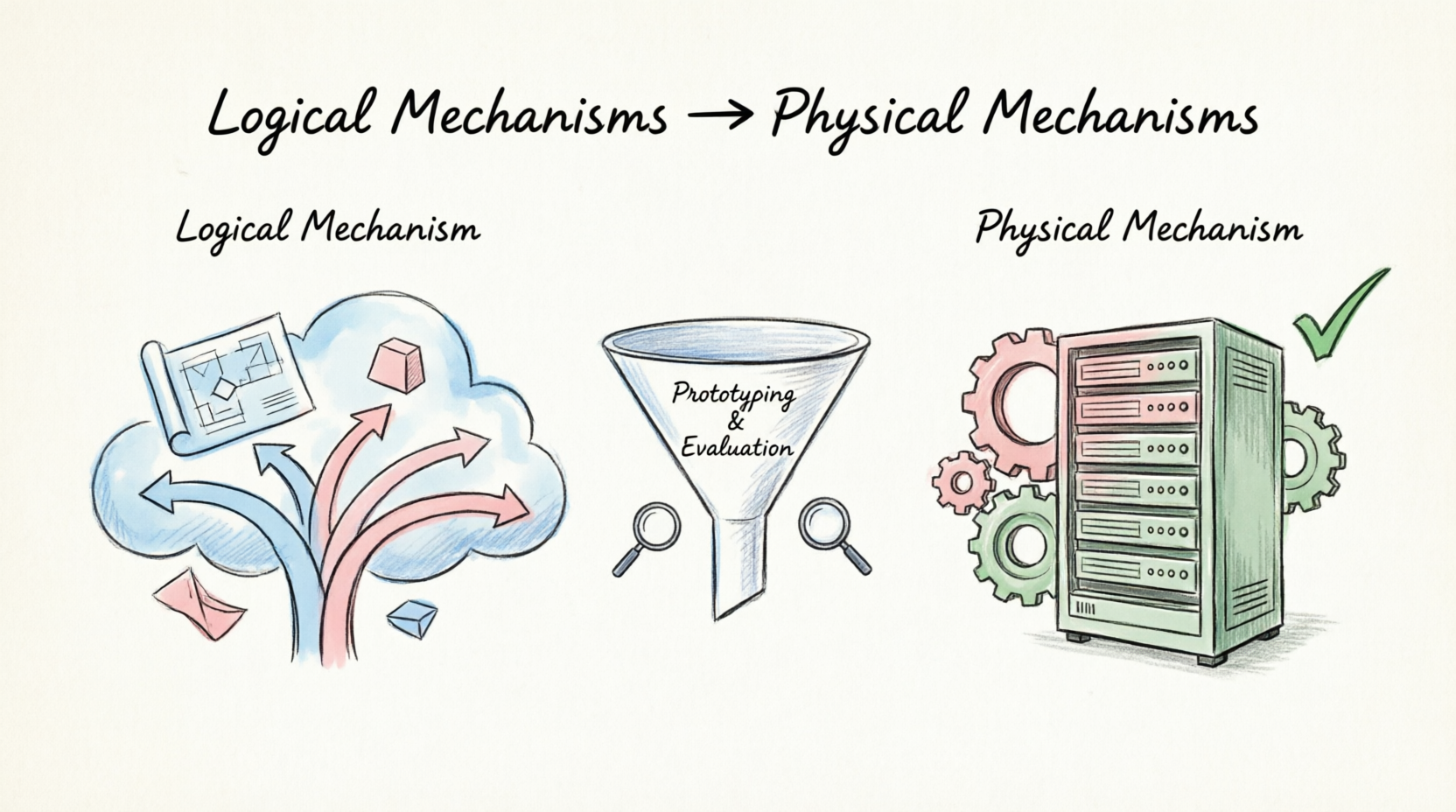
Mechanisms exist on a spectrum of specificity. At one end, we find Logical Mechanisms, which capture the essential characteristics of a solution without committing to a particular technology. At the other end, we find Physical Mechanisms, which represent a firm, vendor-specific implementation commitment.
This guide explores the distinction between logical and physical mechanisms through the lens of the Unified Modeling Language (UML), providing architects and developers with a structured methodology for navigating the design-to-implementation continuum. We will examine key concepts, explore numerous real-world examples, and present a rich collection of UML diagrams authored in PlantUML syntax, compatible with Visual Paradigm and other industry-standard modeling tools.
Why does this matter?
By separating logical design decisions from physical implementation commitments, development teams gain the flexibility to substitute one specific implementation for another during the design phase — without adversely impacting the broader solution. This tiered approach is the cornerstone of maintainable, evolvable, and technology-agnostic architectures.
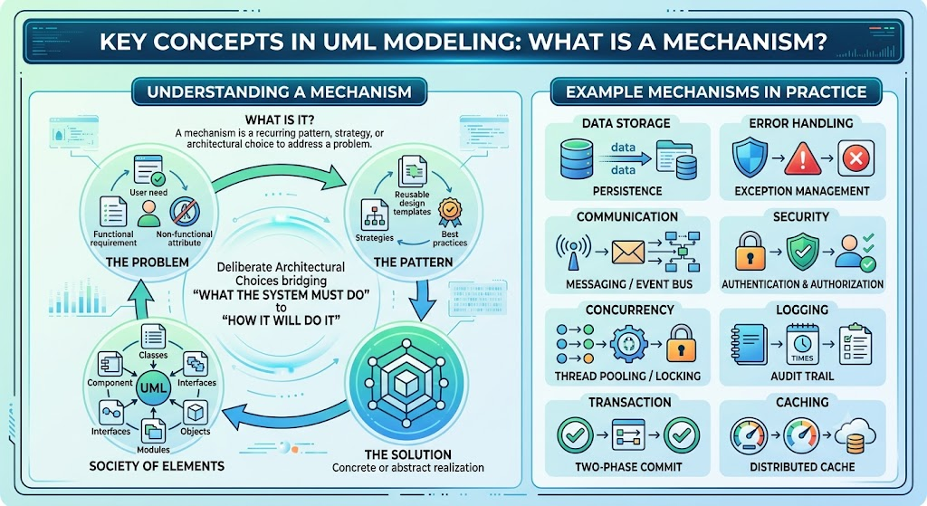
A mechanism is a recurring pattern or strategy applied within a system to address a specific problem or fulfill a required capability. Mechanisms are not ad-hoc solutions; they are deliberate architectural choices that bridge the gap between what the system must do and how it will do it.
| Aspect | Description |
|---|---|
| Problem | A functional or non-functional requirement the system must satisfy |
| Pattern | A reusable approach to solving the problem |
| Society of Elements | The set of classes, components, or modules involved |
| Solution | The concrete or abstract realization of the pattern |
| Problem Domain | Example Mechanism |
|---|---|
| Data Storage | Persistence |
| Error Handling | Exception Management |
| Communication | Messaging / Event Bus |
| Security | Authentication & Authorization |
| Concurrency | Thread Pooling / Locking |
| Logging | Audit Trail |
| Transaction | Two-Phase Commit |
| Caching | Distributed Cache |
A Logical Mechanism captures the key characteristics of a solution while assuming only a general implementation environment. It does not assume a specific technology, vendor, or product.
✅ Identify various options for satisfying a capability
✅ Remain technology-agnostic
✅ Focus on behavior and responsibility, not implementation
✅ Allow multiple physical candidates to be evaluated later
✅ Serve as a bridge between conceptual models and physical designs
| Domain | Logical Mechanism | Possible Physical Candidates |
|---|---|---|
| Persistence | Relational Database | PostgreSQL, MySQL, Oracle, SQL Server |
| Persistence | Object Database | ObjectDB, Versant, db4o |
| Messaging | Asynchronous Message Queue | RabbitMQ, Apache Kafka, ActiveMQ, AWS SQS |
| Security | Identity Provider | Keycloak, Auth0, Okta, Azure AD |
| Caching | Distributed Cache | Redis, Memcached, Hazelcast |
| Search | Full-Text Search Engine | Elasticsearch, Apache Solr, Meilisearch |
| Logging | Centralized Log Aggregator | Splunk, ELK Stack, Datadog |
| API Gateway | Reverse Proxy / Gateway | Kong, NGINX, AWS API Gateway |
A Physical Mechanism is a further refinement of a logical mechanism. It specifies an exact solution implementation — a specific product, library, service, or technology that will be committed to in the final system.
✅ Specify a concrete vendor or product
✅ Represent the final technical commitment
✅ Are often selected through prototyping of logical alternatives
✅ Include version numbers, configurations, and deployment specifics
✅ Lock in dependencies and integration contracts
| Logical Mechanism | Physical Mechanism (Commitment) |
|---|---|
| Relational Database | PostgreSQL 16 on AWS RDS |
| Message Queue | Apache Kafka 3.7 cluster (3 brokers) |
| Identity Provider | Keycloak 24 deployed on Kubernetes |
| Distributed Cache | Redis 7.2 in cluster mode |
| Search Engine | Elasticsearch 8.13 with 5-node cluster |
| API Gateway | Kong 3.5 with PostgreSQL backend |
| Container Orchestration | Kubernetes 1.30 on EKS |
The movement from logical to physical is not a single leap — it is a structured refinement process involving evaluation, prototyping, and justification.
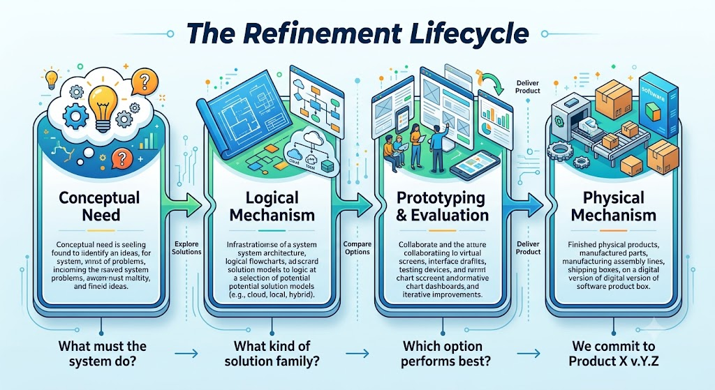
Below is a comprehensive collection of UML diagrams illustrating the logical-to-physical mechanism progression. Each diagram is provided in PlantUML syntax and can be rendered directly in Visual Paradigm (which supports PlantUML import) or any PlantUML-compatible tool.
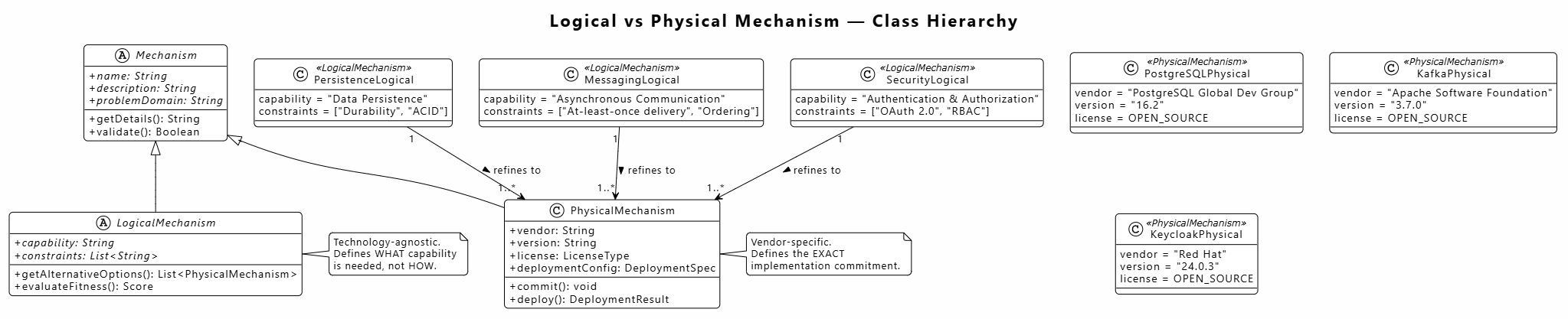
This class diagram models the fundamental relationship between logical and physical mechanisms as an inheritance hierarchy.
@startuml logical_physical_class_diagram
!theme plain
skinparam backgroundColor #FEFEFE
skinparam classAttributeIconSize 0
skinparam shadowing false
skinparam roundcorner 10
skinparam defaultFontName "Segoe UI"

title Logical vs Physical Mechanism — Class Hierarchy

abstract class Mechanism {
  +{abstract} name: String
  +{abstract} description: String
  +{abstract} problemDomain: String
  +getDetails(): String
  +validate(): Boolean
}

abstract class LogicalMechanism extends Mechanism {
  +{abstract} capability: String
  +{abstract} constraints: List<String>
  +getAlternativeOptions(): List<PhysicalMechanism>
  +evaluateFitness(): Score
}

class PhysicalMechanism extends Mechanism {
  +vendor: String
  +version: String
  +license: LicenseType
  +deploymentConfig: DeploymentSpec
  +commit(): void
  +deploy(): DeploymentResult
}

class PersistenceLogical <<LogicalMechanism>> {
  capability = "Data Persistence"
  constraints = ["Durability", "ACID"]
}

class MessagingLogical <<LogicalMechanism>> {
  capability = "Asynchronous Communication"
  constraints = ["At-least-once delivery", "Ordering"]
}

class SecurityLogical <<LogicalMechanism>> {
  capability = "Authentication & Authorization"
  constraints = ["OAuth 2.0", "RBAC"]
}

class PostgreSQLPhysical <<PhysicalMechanism>> {
  vendor = "PostgreSQL Global Dev Group"
  version = "16.2"
  license = OPEN_SOURCE
}

class KafkaPhysical <<PhysicalMechanism>> {
  vendor = "Apache Software Foundation"
  version = "3.7.0"
  license = OPEN_SOURCE
}

class KeycloakPhysical <<PhysicalMechanism>> {
  vendor = "Red Hat"
  version = "24.0.3"
  license = OPEN_SOURCE
}

PersistenceLogical "1" --> "1..*" PhysicalMechanism : refines to >
MessagingLogical "1" --> "1..*" PhysicalMechanism : refines to >
SecurityLogical "1" --> "1..*" PhysicalMechanism : refines to >

note right of LogicalMechanism
  Technology-agnostic.
  Defines WHAT capability
  is needed, not HOW.
end note

note right of PhysicalMechanism
  Vendor-specific.
  Defines the EXACT
  implementation commitment.
end note

@enduml
This component diagram shows how logical components are realized by physical components across architectural layers.
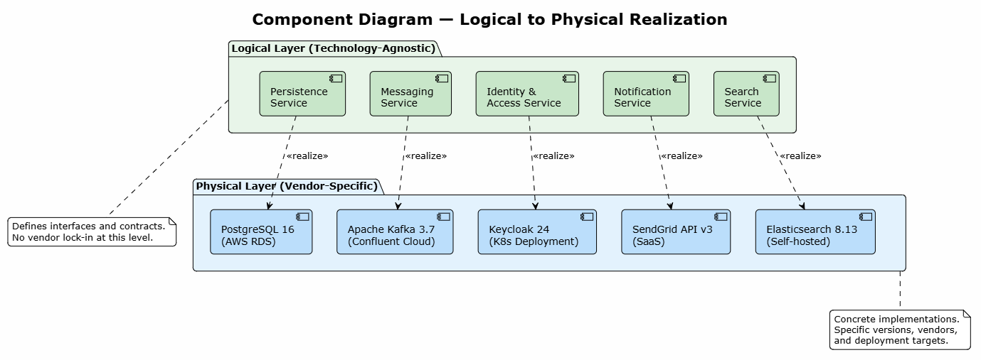
@startuml component_logical_physical
!theme plain
skinparam backgroundColor #FEFEFE
skinparam shadowing false
skinparam roundcorner 10

title Component Diagram — Logical to Physical Realization

package "Logical Layer (Technology-Agnostic)" as LogicalLayer #E8F5E9 {
  component [Persistence\nService] as LPersist #C8E6C9
  component [Messaging\nService] as LMsg #C8E6C9
  component [Identity &\nAccess Service] as LAuth #C8E6C9
  component [Notification\nService] as LNotify #C8E6C9
  component [Search\nService] as LSearch #C8E6C9
}

package "Physical Layer (Vendor-Specific)" as PhysicalLayer #E3F2FD {
  component [PostgreSQL 16\n(AWS RDS)] as PPersist #BBDEFB
  component [Apache Kafka 3.7\n(Confluent Cloud)] as PMsg #BBDEFB
  component [Keycloak 24\n(K8s Deployment)] as PAuth #BBDEFB
  component [SendGrid API v3\n(SaaS)] as PNotify #BBDEFB
  component [Elasticsearch 8.13\n(Self-hosted)] as PSearch #BBDEFB
}

LPersist ..> PPersist : <<realize>>
LMsg ..> PMsg : <<realize>>
LAuth ..> PAuth : <<realize>>
LNotify ..> PNotify : <<realize>>
LSearch ..> PSearch : <<realize>>

note bottom of LogicalLayer
  Defines interfaces and contracts.
  No vendor lock-in at this level.
end note

note bottom of PhysicalLayer
  Concrete implementations.
  Specific versions, vendors,
  and deployment targets.
end note

@enduml
This package diagram illustrates how logical and physical mechanisms are organized into distinct packages to enforce separation of concerns.
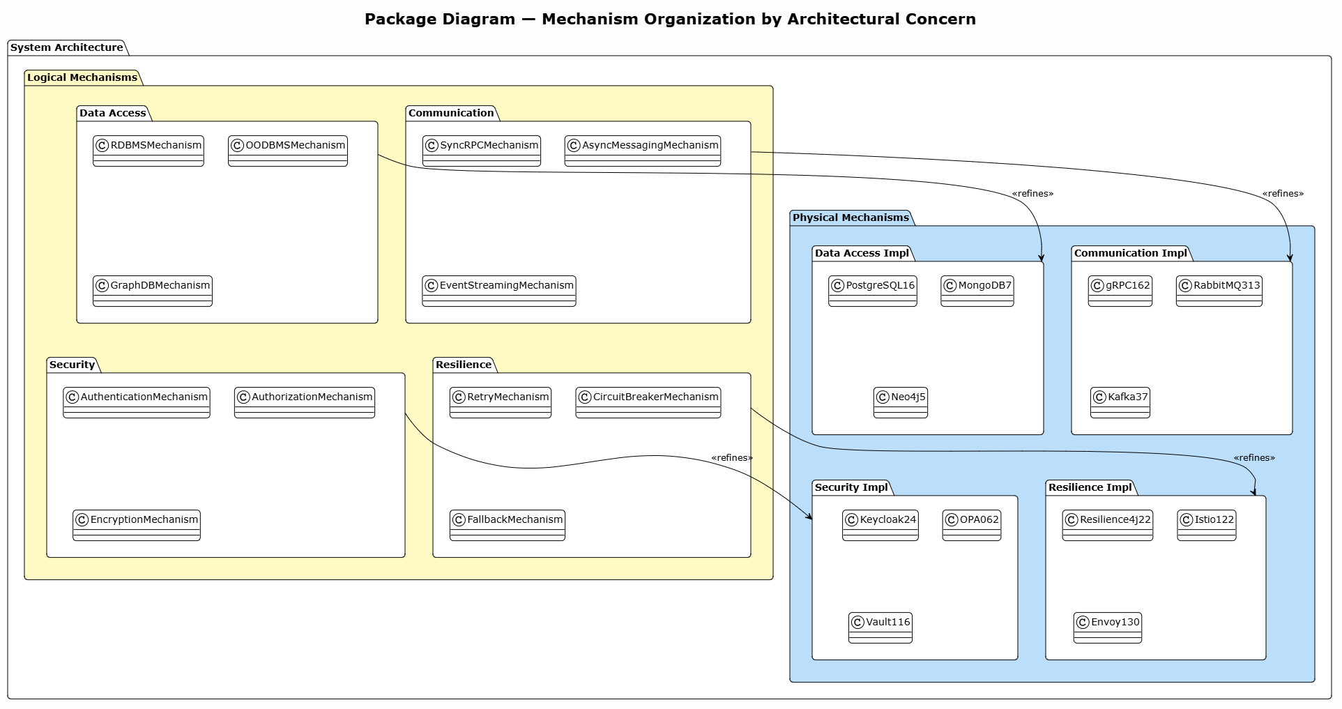
@startuml package_diagram
!theme plain
skinparam backgroundColor #FEFEFE
skinparam shadowing false
skinparam roundcorner 10

title Package Diagram — Mechanism Organization by Architectural Concern

package "System Architecture" as SysArch {

  package "Logical Mechanisms" as LogPkg #FFF9C4 {
    package "Data Access" as LogData {
      class RDBMSMechanism
      class OODBMSMechanism
      class GraphDBMechanism
    }
    package "Communication" as LogComm {
      class SyncRPCMechanism
      class AsyncMessagingMechanism
      class EventStreamingMechanism
    }
    package "Security" as LogSec {
      class AuthenticationMechanism
      class AuthorizationMechanism
      class EncryptionMechanism
    }
    package "Resilience" as LogRes {
      class RetryMechanism
      class CircuitBreakerMechanism
      class FallbackMechanism
    }
  }

  package "Physical Mechanisms" as PhysPkg #BBDEFB {
    package "Data Access Impl" as PhysData {
      class PostgreSQL16
      class MongoDB7
      class Neo4j5
    }
    package "Communication Impl" as PhysComm {
      class gRPC162
      class RabbitMQ313
      class Kafka37
    }
    package "Security Impl" as PhysSec {
      class Keycloak24
      class OPA062
      class Vault116
    }
    package "Resilience Impl" as PhysRes {
      class Resilience4j22
      class Istio122
      class Envoy130
    }
  }
}

LogData --> PhysData : <<refines>>
LogComm --> PhysComm : <<refines>>
LogSec --> PhysSec : <<refines>>
LogRes --> PhysRes : <<refines>>

@enduml
This use case diagram shows how different stakeholders interact with logical and physical mechanisms at different phases.
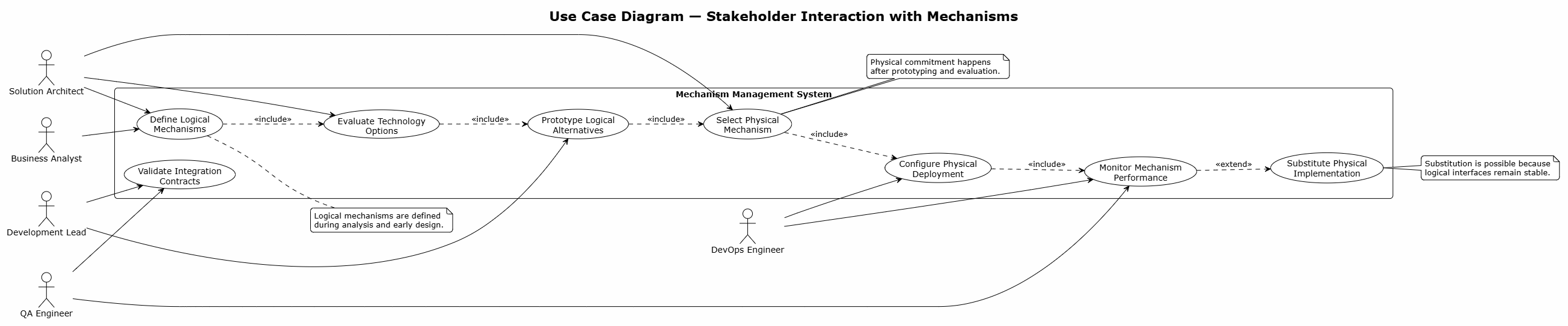
@startuml usecase_diagram
!theme plain
skinparam backgroundColor #FEFEFE
skinparam shadowing false
skinparam roundcorner 10

title Use Case Diagram — Stakeholder Interaction with Mechanisms

left to right direction

actor "Business Analyst" as BA
actor "Solution Architect" as SA
actor "Development Lead" as DL
actor "DevOps Engineer" as DO
actor "QA Engineer" as QA

rectangle "Mechanism Management System" {

  usecase "Define Logical\nMechanisms" as UC1
  usecase "Evaluate Technology\nOptions" as UC2
  usecase "Prototype Logical\nAlternatives" as UC3
  usecase "Select Physical\nMechanism" as UC4
  usecase "Configure Physical\nDeployment" as UC5
  usecase "Validate Integration\nContracts" as UC6
  usecase "Monitor Mechanism\nPerformance" as UC7
  usecase "Substitute Physical\nImplementation" as UC8
}

BA --> UC1
SA --> UC1
SA --> UC2
SA --> UC4
DL --> UC3
DL --> UC6
DO --> UC5
DO --> UC7
QA --> UC6
QA --> UC7

UC1 ..> UC2 : <<include>>
UC2 ..> UC3 : <<include>>
UC3 ..> UC4 : <<include>>
UC4 ..> UC5 : <<include>>
UC5 ..> UC7 : <<include>>
UC7 ..> UC8 : <<extend>>

note right of UC1
  Logical mechanisms are defined
  during analysis and early design.
end note

note right of UC4
  Physical commitment happens
  after prototyping and evaluation.
end note

note right of UC8
  Substitution is possible because
  logical interfaces remain stable.
end note

@enduml
This sequence diagram illustrates the step-by-step process of refining a logical mechanism into a physical one.
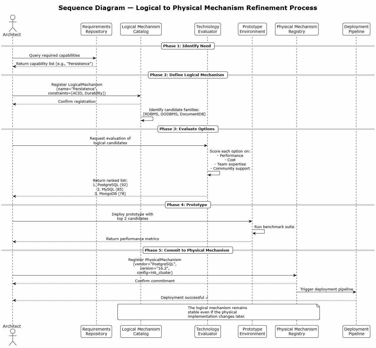
@startuml sequence_refinement
!theme plain
skinparam backgroundColor #FEFEFE
skinparam shadowing false
skinparam roundcorner 10
skinparam sequenceMessageAlign center

title Sequence Diagram — Logical to Physical Mechanism Refinement Process

actor "Architect" as Arch
participant "Requirements\nRepository" as Req
participant "Logical Mechanism\nCatalog" as LogCat
participant "Technology\nEvaluator" as TechEval
participant "Prototype\nEnvironment" as Proto
participant "Physical Mechanism\nRegistry" as PhysReg
participant "Deployment\nPipeline" as Deploy

== Phase 1: Identify Need ==
Arch -> Req: Query required capabilities
Req --> Arch: Return capability list (e.g., "Persistence")

== Phase 2: Define Logical Mechanism ==
Arch -> LogCat: Register LogicalMechanism\n(name="Persistence",\nconstraints=[ACID, Durability])
LogCat --> Arch: Confirm registration
LogCat -> LogCat: Identify candidate families:\n[RDBMS, OODBMS, DocumentDB]

== Phase 3: Evaluate Options ==
Arch -> TechEval: Request evaluation of\nlogical candidates
TechEval -> TechEval: Score each option on:\n- Performance\n- Cost\n- Team expertise\n- Community support
TechEval --> Arch: Return ranked list:\n1. PostgreSQL (92)\n2. MySQL (85)\n3. MongoDB (78)

== Phase 4: Prototype ==
Arch -> Proto: Deploy prototype with\ntop 2 candidates
Proto -> Proto: Run benchmark suite
Proto --> Arch: Return performance metrics

== Phase 5: Commit to Physical Mechanism ==
Arch -> PhysReg: Register PhysicalMechanism\n(vendor="PostgreSQL",\nversion="16.2",\nconfig=HA_cluster)
PhysReg --> Arch: Confirm commitment
PhysReg -> Deploy: Trigger deployment pipeline
Deploy --> Arch: Deployment successful ✓

note over LogCat, PhysReg
  The logical mechanism remains
  stable even if the physical
  implementation changes later.
end note

@enduml
This state machine diagram models the lifecycle of a mechanism as it evolves from concept to committed implementation.
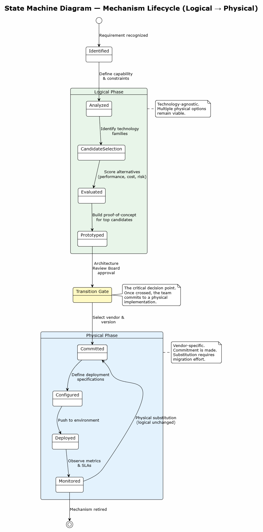
@startuml state_machine_lifecycle
!theme plain
skinparam backgroundColor #FEFEFE
skinparam shadowing false
skinparam roundcorner 10

title State Machine Diagram — Mechanism Lifecycle (Logical → Physical)

[*] --> Identified : Requirement recognized

state "Logical Phase" as LogicalPhase #E8F5E9 {
  Identified --> Analyzed : Define capability\n& constraints
  Analyzed --> CandidateSelection : Identify technology\nfamilies
  CandidateSelection --> Evaluated : Score alternatives\n(performance, cost, risk)
  Evaluated --> Prototyped : Build proof-of-concept\nfor top candidates
}

state "Transition Gate" as Gate #FFF9C4
Prototyped --> Gate : Architecture\nReview Board\napproval

state "Physical Phase" as PhysicalPhase #E3F2FD {
  Gate --> Committed : Select vendor &\nversion
  Committed --> Configured : Define deployment\nspecifications
  Configured --> Deployed : Push to environment
  Deployed --> Monitored : Observe metrics\n& SLAs
}

Monitored --> Committed : Physical substitution\n(logical unchanged)
Monitored --> [*] : Mechanism retired

note right of LogicalPhase
  Technology-agnostic.
  Multiple physical options
  remain viable.
end note

note right of PhysicalPhase
  Vendor-specific.
  Commitment is made.
  Substitution requires
  migration effort.
end note

note right of Gate
  The critical decision point.
  Once crossed, the team
  commits to a physical
  implementation.
end note

@enduml
This activity diagram models the decision-making workflow for selecting a physical mechanism from logical candidates.
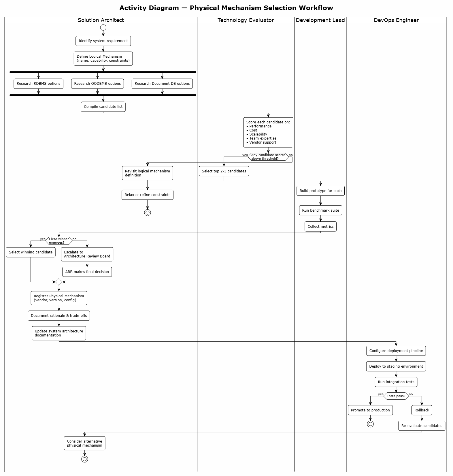
@startuml activity_decision
!theme plain
skinparam backgroundColor #FEFEFE
skinparam shadowing false
skinparam roundcorner 10

title Activity Diagram — Physical Mechanism Selection Workflow

|Solution Architect|
start
:Identify system requirement;
:Define Logical Mechanism\n(name, capability, constraints);

fork
  :Research RDBMS options;
fork again
  :Research OODBMS options;
fork again
  :Research Document DB options;
end fork

:Compile candidate list;

|Technology Evaluator|
:Score each candidate on:\n• Performance\n• Cost\n• Scalability\n• Team expertise\n• Vendor support;

if (Any candidate scores\nabove threshold?) then (yes)
  :Select top 2-3 candidates;

  |Development Lead|
  :Build prototype for each;
  :Run benchmark suite;
  :Collect metrics;

  |Solution Architect|
  if (Clear winner\nemerges?) then (yes)
    :Select winning candidate;
  else (no)
    :Escalate to\nArchitecture Review Board;
    :ARB makes final decision;
  endif

  |Solution Architect|
  :Register Physical Mechanism\n(vendor, version, config);
  :Document rationale & trade-offs;
  :Update system architecture\ndocumentation;

  |DevOps Engineer|
  :Configure deployment pipeline;
  :Deploy to staging environment;
  :Run integration tests;

  if (Tests pass?) then (yes)
    :Promote to production;
    stop
  else (no)
    :Rollback;
    :Re-evaluate candidates;
    |Solution Architect|
    :Consider alternative\nphysical mechanism;
    stop
  endif

else (no)
  :Revisit logical mechanism\ndefinition;
  :Relax or refine constraints;
  stop
endif

@enduml
This deployment diagram shows how physical mechanisms are deployed onto concrete infrastructure nodes.

@startuml deployment_diagram
!theme plain
skinparam backgroundColor #FEFEFE
skinparam shadowing false
skinparam roundcorner 10

title Deployment Diagram — Physical Mechanisms on Infrastructure

node "AWS Cloud" as AWS #E3F2FD {

  node "Application Tier\n(EKS Kubernetes 1.30)" as AppTier #BBDEFB {
    artifact "Order Service\n(Spring Boot 3.3)" as OrderSvc
    artifact "Payment Service\n(Spring Boot 3.3)" as PaySvc
    artifact "Notification Service\n(Node.js 20)" as NotifSvc
  }

  node "Data Tier" as DataTier #C8E6C9 {
    database "PostgreSQL 16\n(AWS RDS - Multi-AZ)" as PG
    database "Redis 7.2\n(ElastiCache Cluster)" as Redis
    database "Elasticsearch 8.13\n(3-node cluster)" as ES
  }

  node "Messaging Tier" as MsgTier #FFF9C4 {
    queue "Apache Kafka 3.7\n(MSK - 3 brokers)" as Kafka
    queue "Amazon SQS" as SQS
  }

  node "Security Tier" as SecTier #FFCDD2 {
    component "Keycloak 24\n(OIDC Provider)" as KC
    component "HashiCorp Vault 1.16\n(Secrets Management)" as Vault
  }
}

cloud "External Services" as Ext #F5F5F5 {
  component "SendGrid\n(Email Delivery)" as SG
  component "Stripe\n(Payment Gateway)" as Stripe
}

OrderSvc --> PG : <<physical>>\nJDBC
OrderSvc --> Redis : <<physical>>\nLettuce client
OrderSvc --> Kafka : <<physical>>\nProducer API
OrderSvc --> KC : <<physical>>\nOIDC
PaySvc --> Stripe : <<physical>>\nREST API
PaySvc --> PG : <<physical>>\nJDBC
NotifSvc --> SG : <<physical>>\nREST API
NotifSvc --> SQS : <<physical>>\nSDK
NotifSvc --> ES : <<physical>>\nREST client
PaySvc --> Vault : <<physical>>\nSecrets API

note right of PG
  Physical Mechanism:
  Persistence via
  PostgreSQL 16 on RDS
  (Logical: RDBMS)
end note

note right of Kafka
  Physical Mechanism:
  Messaging via
  Kafka 3.7 on MSK
  (Logical: Async Queue)
end note

note right of KC
  Physical Mechanism:
  Auth via Keycloak 24
  (Logical: Identity Provider)
end note

@enduml
This communication (interaction) diagram shows how mechanisms interact at runtime to fulfill a business scenario.
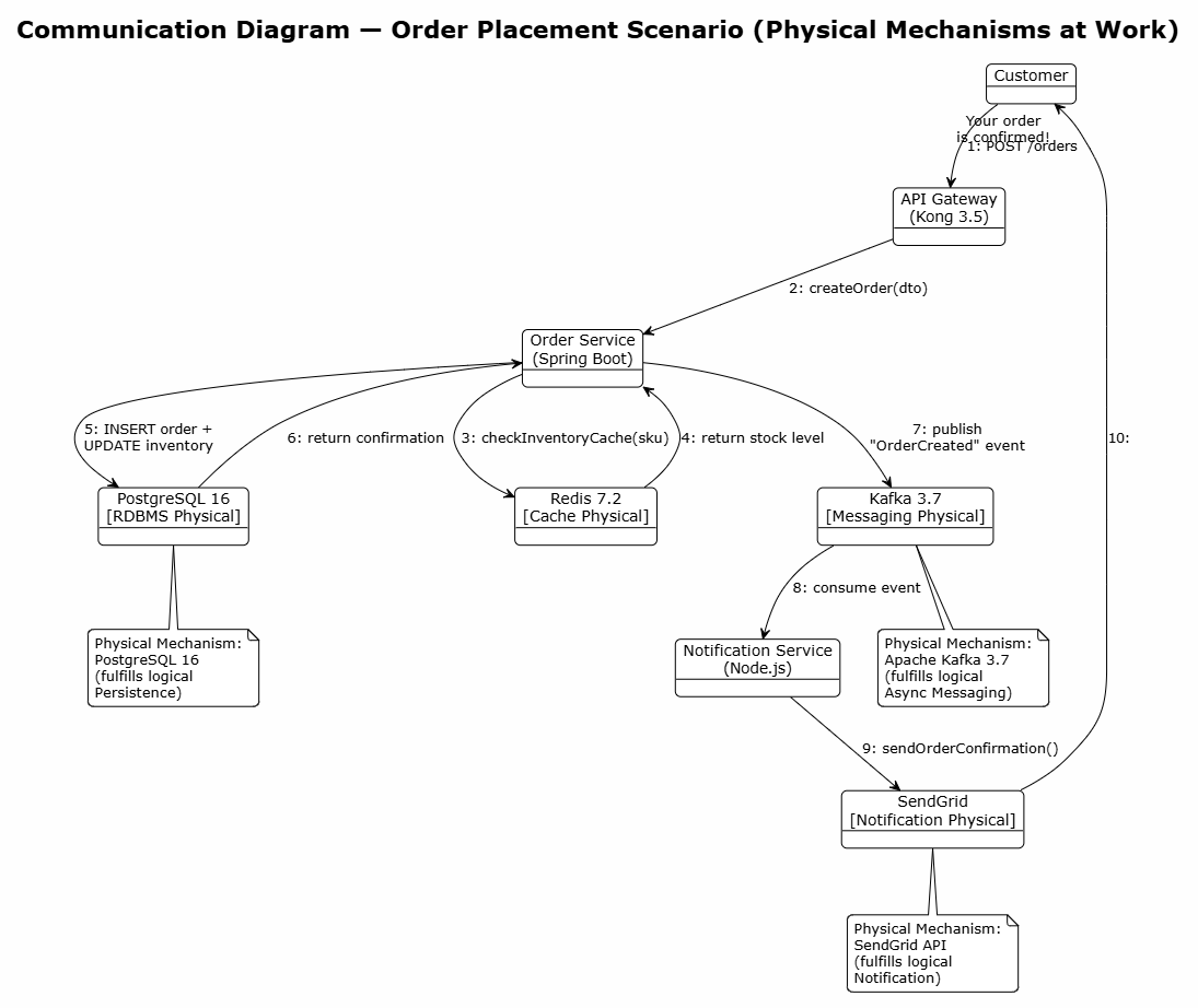
@startuml communication_diagram
!theme plain
skinparam backgroundColor #FEFEFE
skinparam shadowing false
skinparam roundcorner 10

title Communication Diagram — Order Placement Scenario (Physical Mechanisms at Work)

object "Customer" as Cust
object "API Gateway\n(Kong 3.5)" as GW
object "Order Service\n(Spring Boot)" as Order
object "PostgreSQL 16\n[RDBMS Physical]" as DB
object "Redis 7.2\n[Cache Physical]" as Cache
object "Kafka 3.7\n[Messaging Physical]" as Kafka
object "Notification Service\n(Node.js)" as Notif
object "SendGrid\n[Notification Physical]" as Email

Cust --> GW : 1: POST /orders
GW --> Order : 2: createOrder(dto)
Order --> Cache : 3: checkInventoryCache(sku)
Cache --> Order : 4: return stock level
Order --> DB : 5: INSERT order +\nUPDATE inventory
DB --> Order : 6: return confirmation
Order --> Kafka : 7: publish\n"OrderCreated" event
Kafka --> Notif : 8: consume event
Notif --> Email : 9: sendOrderConfirmation()
Email --> Cust : 10: "Your order\nis confirmed!"

note bottom of DB
  Physical Mechanism:
  PostgreSQL 16
  (fulfills logical
  Persistence)
end note

note bottom of Kafka
  Physical Mechanism:
  Apache Kafka 3.7
  (fulfills logical
  Async Messaging)
end note

note bottom of Email
  Physical Mechanism:
  SendGrid API
  (fulfills logical
  Notification)
end note

@enduml
This composite structure diagram shows the internal structure of a mechanism, revealing how logical ports connect to physical adapters.
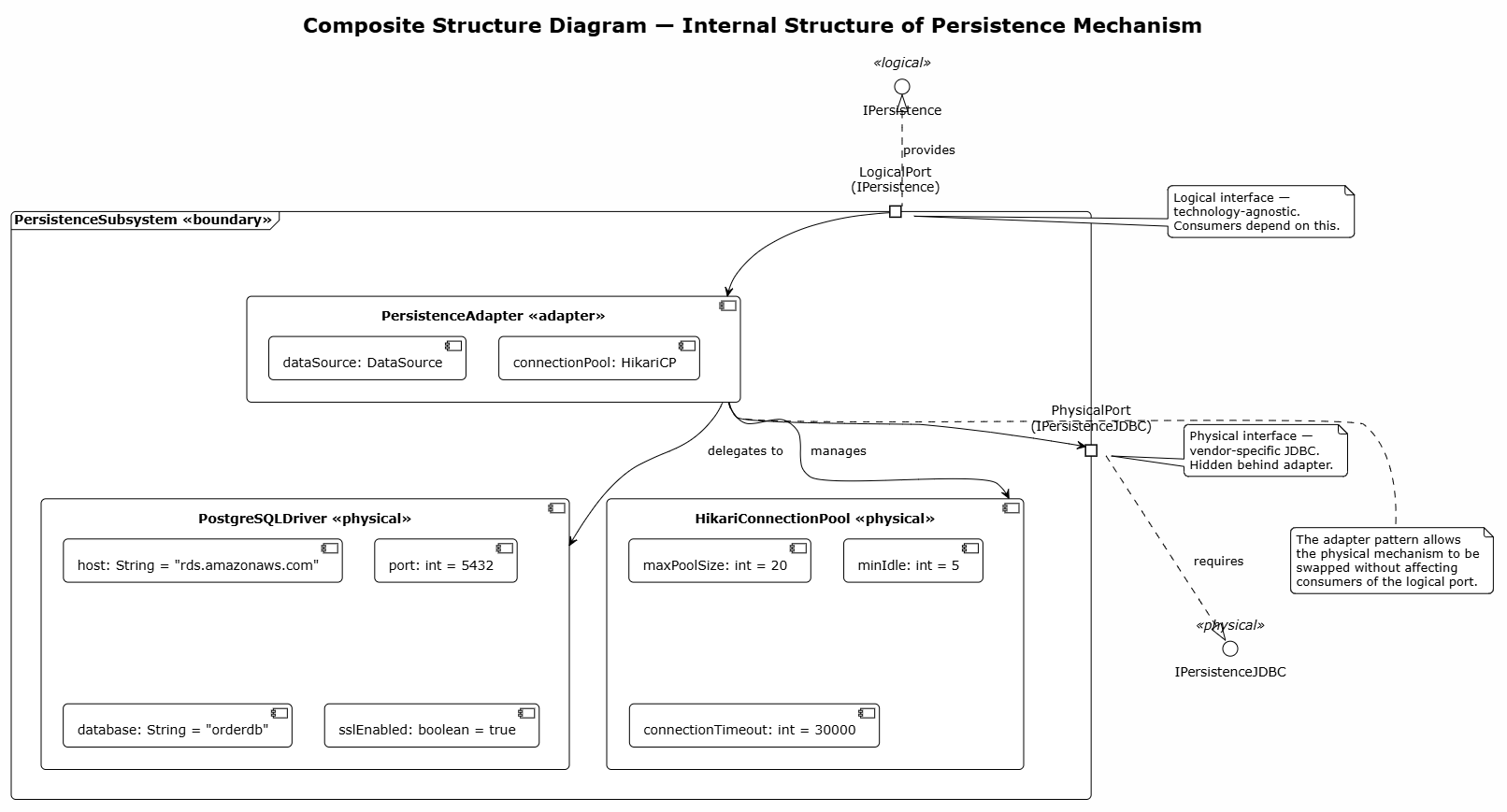
@startuml composite_structure
!theme plain
skinparam backgroundColor #FEFEFE
skinparam shadowing false
skinparam roundcorner 10

title Composite Structure Diagram — Internal Structure of Persistence Mechanism

interface "IPersistence" as IPersistence <<logical>>
interface "IPersistenceJDBC" as IPersistenceJDBC <<physical>>

frame "PersistenceSubsystem <<boundary>>" as PersistenceSubsystem {
portin "LogicalPort\n(IPersistence)" as LPort
portout "PhysicalPort\n(IPersistenceJDBC)" as PPort

component "PersistenceAdapter <<adapter>>" as PersistenceAdapter {
[dataSource: DataSource]
[connectionPool: HikariCP]
}

component "PostgreSQLDriver <<physical>>" as PostgreSQLDriver {
[host: String = "rds.amazonaws.com"]
[port: int = 5432]
[database: String = "orderdb"]
[sslEnabled: boolean = true]
}

component "HikariConnectionPool <<physical>>" as HikariConnectionPool {
[maxPoolSize: int = 20]
[minIdle: int = 5]
[connectionTimeout: int = 30000]
}

' Internal wiring inside composite boundary
LPort --> PersistenceAdapter
PersistenceAdapter --> PPort : uses
PersistenceAdapter --> PostgreSQLDriver : delegates to
PersistenceAdapter --> HikariConnectionPool : manages
}

' External Interface Realizations
IPersistence <|.. LPort : provides PPort ..|> IPersistenceJDBC : requires

' Notes
note right of LPort
Logical interface —
technology-agnostic.
Consumers depend on this.
end note

note right of PPort
Physical interface —
vendor-specific JDBC.
Hidden behind adapter.
end note

note bottom of PersistenceAdapter
The adapter pattern allows
the physical mechanism to be
swapped without affecting
consumers of the logical port.
end note

@endumlVisual Paradigm is a comprehensive UML modeling tool that fully supports the creation and management of logical and physical mechanism diagrams. Below is guidance on leveraging its features for this purpose.
| Feature | How It Helps |
|---|---|
| PlantUML Import | Paste PlantUML code directly into Visual Paradigm to auto-generate diagrams |
| Diagram Navigation | Navigate between logical and physical diagrams via hyperlinked elements |
| Model Repository | Store logical and physical mechanisms in a centralized, versioned repository |
| Traceability Matrix | Link logical mechanisms to physical implementations for impact analysis |
| Code Generation | Generate skeleton code from physical mechanism class diagrams |
| Reverse Engineering | Import existing code to discover physical mechanisms already in use |
| Stereotype Support | Apply <<logical>> and <<physical>> stereotypes to UML elements |
| Team Collaboration | Multiple architects can collaborate on mechanism refinement simultaneously |
| Report Generation | Produce architecture documentation showing logical-to-physical mappings |
1. Create a new UML Project → "System Architecture"
2. Define Logical Mechanisms in a Class Diagram (stereotype: <<logical>>)
3. Create a Package Diagram to organize mechanisms by concern
4. Build a Component Diagram showing logical components
5. Prototype and evaluate → select physical mechanisms
6. Create a second Component Diagram for physical components (stereotype: <<physical>>)
7. Link logical ↔ physical using <<realize>> dependencies
8. Generate Deployment Diagram for physical infrastructure
9. Use Sequence/Communication diagrams to validate runtime behavior
10. Export documentation and share with stakeholders
Open Visual Paradigm
Go to Tools → PlantUML → Import from PlantUML
Paste any of the PlantUML code blocks from this guide
Click Generate Diagram
The diagram is rendered and fully editable within Visual Paradigm
| Dimension | Logical Mechanism | Physical Mechanism |
|---|---|---|
| Specification Level | General capability description | Exact vendor/product/version |
| Technology Binding | None (agnostic) | Fully bound |
| Flexibility | High — multiple options remain | Low — commitment made |
| Phase of Use | Analysis & Early Design | Detailed Design & Implementation |
| Stakeholders | Business Analysts, Architects | Developers, DevOps, DBAs |
| Change Cost | Low (swap candidate) | High (migration required) |
| UML Stereotype | <<logical>> |
<<physical>> |
| Example | "Relational Database" | "PostgreSQL 16 on AWS RDS" |
| Diagram Types | Class, Package, Use Case | Component, Deployment, Sequence |
| Documentation | Architecture Decision Records | Deployment Runbooks, Config Files |
The distinction between logical mechanisms and physical mechanisms is one of the most powerful conceptual tools available to systems architects. By deliberately separating what a system needs to do from how it will specifically do it, teams unlock a range of critical benefits:
Flexibility — Logical mechanisms allow multiple physical implementations to be evaluated without prematurely constraining the design space.
Reduced Risk — Prototyping logical alternatives before committing to a physical mechanism prevents costly rework caused by premature technology decisions.
Substitutability — Because logical interfaces remain stable, physical implementations can be swapped (e.g., migrating from one database vendor to another) with minimal impact on the broader architecture.
Clear Communication — Logical mechanisms speak the language of business and capability; physical mechanisms speak the language of engineering and deployment. This separation enables effective dialogue across all stakeholder groups.
Evolvability — As technology landscapes shift, systems built on well-defined logical mechanisms can adapt by updating physical commitments without rewriting architectural foundations.
The UML diagrams presented in this guide — spanning class, component, package, use case, sequence, state machine, activity, deployment, communication, and composite structure diagrams — provide a complete visual toolkit for modeling this progression. When combined with a robust tool like Visual Paradigm, architects can maintain full traceability from abstract requirement to concrete deployment.
Final Thought: The best architectures are not those that pick the "right" technology first — they are those that delay the commitment just long enough to make an informed, evidence-based decision. Logical mechanisms are the instrument by which this disciplined delay is achieved.
This guide was structured for use with Visual Paradigm and PlantUML. All diagram code blocks can be directly imported and rendered within the tool.

