Bridging business scope and technical implementation with clear, maintainable architecture diagrams.
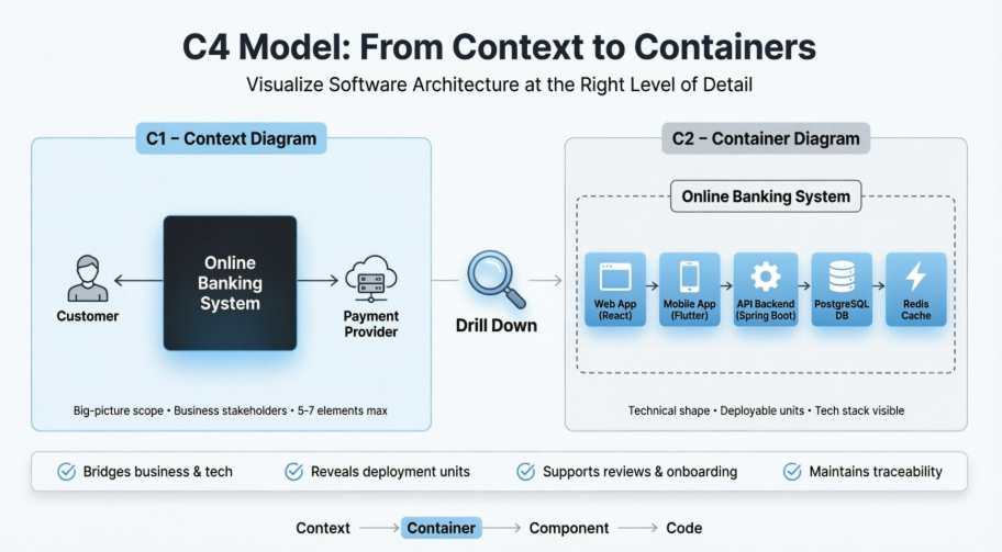
The C4 Model (created by Simon Brown) provides a hierarchical approach to visualizing software architecture. By moving from a System Context Diagram (Level 1) to a Container Diagram (Level 2), teams translate high-level business interactions into actionable technical blueprints. This guide walks you through the practical, step-by-step process of drilling down in Visual Paradigm, ensuring consistency, clarity, and traceability across architecture artifacts.
Drilling down from Context to Container isn’t just about adding boxes and arrows. It’s a deliberate architectural exercise that delivers measurable value:
| Benefit | Impact |
|---|---|
| Scope-to-Implementation Bridge | Aligns stakeholder expectations with engineering reality. |
| Early Technology Visibility | Surfaces stack choices (e.g., React, Spring Boot, PostgreSQL) before coding begins. |
| Deployment & Integration Mapping | Clarifies boundaries, sync/async flows, and third-party dependencies. |
| Risk & Compliance Readiness | Highlights security perimeters, data sovereignty, and scalability bottlenecks. |
| Team Alignment | Accelerates onboarding, architecture reviews, threat modeling, and DevOps planning. |
Best Practice: Create the Context diagram first. Drill down only into primary systems in scope. Keep Container diagrams focused: 5–10 containers maximum for optimal readability.
The Context diagram treats your system as a single black box. It must be accurate before you decompose it.
In Visual Paradigm:
Diagram > New > C4 > System Context Diagram (or use the C4 Template Gallery).Customer, Support Agent, Admin).Payment Gateway, Core Banking API).Submits payments via HTTPS, Syncs user profiles via OAuth2).💡 VP Tip: Use the dedicated C4 Shape Library. Leverage VP’s AI-assisted generation by describing your scope in natural language to bootstrap a draft, then refine manually.
A C4 Container is not a Docker/Kubernetes container. It represents any independently deployable or runnable unit that holds code or data.
Key Questions to Answer:
Documentation Practice: Assign one primary responsibility per container. Record technology stack, hosting model, and communication patterns in element properties or linked Architecture Decision Records (ADRs).
Choose the workflow that best fits your team’s maturity and timeline:
Diagram > New > C4 > Container DiagramPersons and Software Systems from your C1 diagram.Prompt example:
Create a C4 Container diagram for an Online Banking System. Inside: Web App (React), Mobile App (Flutter), API Backend (Spring Boot), PostgreSQL DB, Redis Cache. Customers interact via web/mobile; external Payment Provider connects to the API.
Refine iteratively: Add a Kafka-based Notification Service or Extract Authentication to a dedicated Auth Container.
In your Context diagram, right-click the central Software System → Create Sub-Diagram > Container Diagram. Visual Paradigm automatically links boundaries and external relationships, preserving hierarchy and model consistency.
For large enterprises, use VP’s OpenAPI or plugin framework to script diagram generation from model repositories or code metadata. Ideal for CI/CD documentation pipelines.
| Validation Step | Action |
|---|---|
| Consistency Check | Verify element names, descriptions, and relationships trace cleanly to C1. |
| Detail Balance | Include tech stack, sync/async style, and key protocols. Omit implementation logic (save for Component level). |
| Layout & Readability | Group by tier (UI → Business Logic → Data). Use sparing, intentional color. Add a legend. |
| Review Cycle | Walk through with developers, DevOps, and stakeholders. Validate responsibilities and integration points. |
| Version Control | Store in VP project, export to PDF/PNG, or sync with Confluence/Jira. Update as architecture evolves. |
| Pattern | Structure | External Integration Points |
|---|---|---|
| Web + Mobile + API + DB | Customer → Web App / Mobile App → API Backend → Database |
Payment/Identity providers connect to API only |
| Microservices | API Gateway → [Order, Inventory, Billing] Services → Shared DBs / Event Bus |
External systems route through Gateway or specific services |
| Hybrid / Strangler Fig | Legacy Monolith + New Reporting Service + Migration Proxy |
Proxy routes traffic; new service reads from replicated data |
| Event-Driven | Producers → Message Broker (Kafka/RabbitMQ) → Consumers → Data Stores |
External systems publish/subscribe to topics/queues |
Example Drill-Down Narrative:
Online Banking System interacts with Customer and External Payment Provider.@startuml
!include <C4/C4_Context>
title System Context Diagram (C1): Online Banking System
' External Actors & Systems
Person(customer, "Customer", "Retail banking client who manages accounts and initiates payments")
System_Ext(payment_provider, "External Payment Provider", "Third-party gateway for payment processing, clearing, and settlement")
' Central Software System (Black Box)
System(banking_system, "Online Banking System", "Provides secure retail banking services via web and mobile channels")
' Relationships
Rel(customer, banking_system, "Accesses accounts & submits payments", "HTTPS / Web & Mobile")
Rel(banking_system, payment_provider, "Routes payment requests & verifies status", "HTTPS / REST API")
@enduml
Customer → Web Application (React) & Mobile App (Flutter) → API Application (Spring Boot) → PostgreSQL & Redis Cache. API communicates with Payment Provider via HTTPS. Async notifications flow through Kafka → Email Service.PlantUML Code:
@startuml
!include <C4/C4_Container>
title Container Diagram: Online Banking System
Person(customer, "Customer", "Banking client accessing services via web or mobile")
System_Ext(payment_provider, "External Payment Provider", "Third-party payment processing & settlement service")
System_Boundary(banking_system, "Online Banking System") {
Container(web_app, "Web Application", "React, TypeScript", "Provides responsive web UI for account management and transactions")
Container(mobile_app, "Mobile App", "Flutter, Dart", "Provides native-feel mobile interface and push notifications")
Container(api_app, "API Application", "Spring Boot, Java", "Core business logic, routing, authentication, and payment orchestration")
ContainerDb(postgres_db, "Customer Database", "PostgreSQL", "Persists accounts, transaction history, and user profiles")
Container(redis_cache, "Redis Cache", "Redis", "Stores session state, rate limits, and frequently accessed data")
Container(kafka_broker, "Message Broker", "Apache Kafka", "Asynchronous event streaming for notifications and audit trails")
Container(email_service, "Email Service", "Node.js, SMTP", "Consumes events to send transactional and security alerts")
}
Rel(customer, web_app, "Uses", "HTTPS")
Rel(customer, mobile_app, "Uses", "HTTPS")
Rel(web_app, api_app, "Submits requests", "HTTPS/REST")
Rel(mobile_app, api_app, "Submits requests", "HTTPS/REST")
Rel(api_app, postgres_db, "Reads/Writes data", "TCP/SQL")
Rel(api_app, redis_cache, "Reads/Writes cache", "TCP/RESP")
Rel(api_app, payment_provider, "Submits payments & verifies", "HTTPS/OAuth2")
Rel(api_app, kafka_broker, "Publishes events", "Async/Kafka")
Rel(kafka_broker, email_service, "Consumes events", "Async/Kafka")
Rel(email_service, customer, "Sends notifications", "SMTP/Email")
@enduml
Technology and Responsibility fields.Now zoom into the API container for a Component view.| Mistake | Consequence | Fix |
|---|---|---|
| Treating “Container” as only Docker/K8s | Misaligned mental model, missing monoliths/batch jobs | Use C4 definition: any deployable/runnable unit |
| Overloading the diagram | Cognitive overload, unreadable layouts | Cap at 5–10 containers. Push details to C3/C4 |
| Inconsistent naming across levels | Broken traceability, stakeholder confusion | Reuse model elements. Audit names before sharing |
| Dropping external systems in C2 | Lost integration context, security blind spots | Keep Persons & External Systems visible; route to correct containers |
| Diagrams in isolation | Siloed documentation, outdated artifacts | Use sub-diagrams, version control, and regular review cycles |
Drilling down from a C4 Context Diagram to a Container Diagram is a disciplined, repeatable process that transforms high-level scope into technical clarity. By leveraging Visual Paradigm’s C4 tooling, model repository, and hierarchical linking features, teams produce architecture documentation that scales alongside the system itself.
Start small. Iterate deliberately. Keep diagrams living artifacts, not static posters. When Context and Container views align, you empower engineers to build confidently, operations to deploy safely, and stakeholders to understand clearly.
For the latest interface details and AI capabilities, refer to Visual Paradigm’s official documentation. Architecture evolves—your diagrams should too.