
In the fast-paced world of software development, ambiguity is the enemy of efficiency. While visual models like use case diagrams provide a high-level overview of system functionality, they often lack the depth required for developers, testers, and stakeholders to fully understand how a feature should behave. This is where the Use Case Description becomes indispensable.
A use case description is a detailed, text-based narrative that captures the step-by-step interactions between an actor (a user or external system) and your system to achieve a specific goal. It serves as the textual counterpart to the visual use case diagram, bridging the gap between abstract concepts and concrete implementation. By clarifying functional requirements, aligning stakeholder expectations, and forming a robust foundation for testing, well-crafted use case descriptions ensure that everyone involved in the project shares a unified understanding of the system’s behavior.
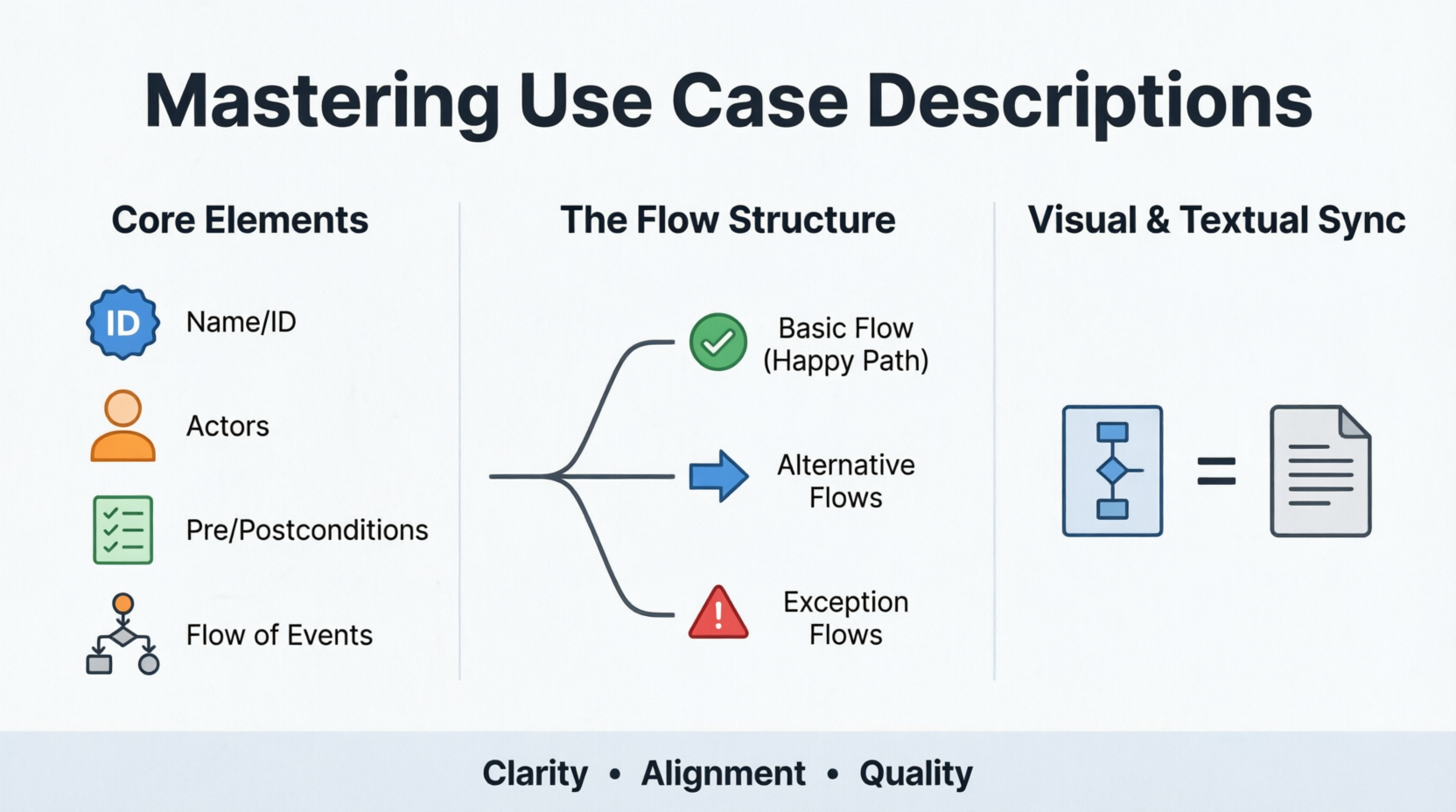
This article provides an in-depth guide to the key concepts, structure, and practical application of use case descriptions, complete with a real-world example and corrected PlantUML visualization.
The use case model is comprised of two primary artifacts:
The Use Case Diagram: The visual representation showing actors, use cases, and their relationships.
The Use Case Description: The textual details providing context, rules, and flows.
While the diagram offers a "bird’s-eye view," the description is where the real value lies. It provides the nuance, business rules, and exception handling that a diagram alone cannot convey.
A well-written use case description typically includes these standard sections:
| Element | Description |
|---|---|
| Use Case Name & ID | A unique name and identifier for the use case, often a verb-noun phrase (e.g., "Place Order" or "Withdraw Cash"). |
| Brief Description | A concise summary of the use case's purpose and what it accomplishes. |
| Actors | The entities (users or other systems) that interact with the use case. The primary actor initiates the interaction, while secondary actors provide a service or information. |
| Preconditions | The conditions that must be true before the use case can begin. For example, "The user is logged into the system." |
| Postconditions | The state of the system after the use case finishes. This can be a successful outcome or a failure state. |
| Flow of Events | The heart of the description, detailing the sequence of steps. It is divided into: • Basic Flow (Happy Path): The "ideal" scenario where everything goes as planned. • Alternative Flows: Less common, but still successful, paths to reach the goal. • Exception Flows: Paths that lead to an unsuccessful conclusion or error condition. |
| Special Requirements | Non-functional requirements (like performance, security, or regulatory) that apply specifically to this use case. |
Creating a comprehensive use case description involves a structured approach to ensure no critical detail is overlooked.
Start by defining the specific goal the user wants to achieve and the primary actor who will initiate the process. Ask: Who is doing this, and why?
Determine what must be in place for the use case to start (preconditions) and what the system's state will be upon completion (postconditions). This sets the boundaries of the use case.
Document the "happy path" step-by-step. For each step, clearly describe:
Who performs the action (actor or system).
What the system’s response is.
Keep the language simple and active.
Elicit other, less common ways to accomplish the same goal successfully. Note exactly where in the basic flow this alternative path would diverge (e.g., "At step 3...").
Identify failure scenarios (e.g., validation errors, system unavailability, network timeouts) and document the system's response, such as specific error messages displayed or rollback procedures.
Let’s apply this framework to a simplified "Place Order" use case for an online retail platform.
Use Case Name: Place Order
ID: UC-101
Description: This use case describes the steps for a registered customer to place an order, including making a payment and receiving a confirmation.
Primary Actor: Customer
Secondary Actor: Payment Gateway
Preconditions:
The customer is logged into the system.
The customer has items in their shopping cart.
Postconditions (Success):
The order is created in the database.
The customer's payment is processed successfully.
A confirmation email is sent to the customer.
The Customer selects the option to proceed to checkout.
The System displays the order summary and shipping details.
The Customer confirms the order and enters payment details.
The System sends the payment details to the Payment Gateway for processing.
The Payment Gateway confirms the successful transaction.
The System finalizes the order and displays an order confirmation number.
The System sends a confirmation email to the Customer.
At step 3, the Customer selects the option to "Pay with Saved Card".
The System proceeds to step 4 using the saved payment details automatically.
At step 4, the Payment Gateway returns a "Declined" message.
The System displays an error message on the screen: "Your payment was declined. Please check your details or use a different payment method."
The use case returns to step 3 to allow the Customer to try again.
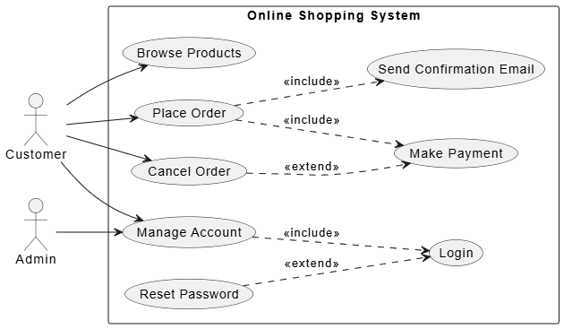
A use case diagram provides the high-level context for these descriptions. PlantUML uses simple text to generate these diagrams, making them easy to maintain in version control and integrate into documentation pipelines.
Below is the corrected PlantUML code corresponding to the Online Shopping System. The previous version contained syntax errors regarding relationship definitions. This version ensures proper syntax for <<include>> and <<extend>> relationships, which require dashed arrows pointing from the base use case to the included/extended use case.
@startuml
' Use Case Diagram for Online Shopping System

left to right direction
' Gives a horizontal layout

' Define actors
actor "Customer" as customer
actor "Admin" as admin

' Define system boundary
rectangle "Online Shopping System" {
  ' Primary use cases
  usecase "Browse Products" as UC1
  usecase "Place Order" as UC2
  usecase "Make Payment" as UC3
  usecase "Cancel Order" as UC4
  usecase "Manage Account" as UC5

  ' Secondary use cases for relationships
  usecase "Login" as SUC1
  usecase "Reset Password" as SUC2
  usecase "Send Confirmation Email" as SUC3
}

' Actor associations (Solid lines)
customer --> UC1
customer --> UC2
customer --> UC4
customer --> UC5
admin --> UC5

' Include relationships (Mandatory)
' Dashed arrow with <<include>> stereotype
' "Place Order" always includes "Make Payment" and "Send Confirmation Email"
UC2 ..> UC3 : <<include>>
UC2 ..> SUC3 : <<include>>

' "Manage Account" always requires "Login"
UC5 ..> SUC1 : <<include>>

' Extend relationships (Optional)
' Dashed arrow with <<extend>> stereotype
' "Reset Password" is an optional extension of "Login"
SUC2 ..> SUC1 : <<extend>>

' "Cancel Order" may optionally involve a refund via "Make Payment" logic
UC4 ..> UC3 : <<extend>>

@enduml
@startuml and @enduml: Mark the beginning and end of the diagram code.
actor "Customer" as customer: Defines an actor with an alias customer for later reference.
rectangle "Online Shopping System" { ... }: Creates the system boundary box, grouping all internal use cases.
usecase "Place Order" as UC2: Defines a use case and assigns it an alias.
customer --> UC2: Creates a solid association line between the actor and the use case.
UC2 ..> UC3 : <<include>>: Creates a dashed arrow (..>) pointing from the base use case (UC2) to the included use case (UC3). This indicates that the behavior of UC3 is always part of UC2. Note: The previous example used .> which can sometimes cause parsing issues depending on the renderer; ..> is the standard explicit syntax for dashed lines.
SUC2 ..> SUC1 : <<extend>>: Creates a dashed arrow (..>) pointing from the extending use case (SUC2) to the base use case (SUC1). This indicates that SUC2 is an optional addition to SUC1, triggered only under specific conditions.
Use case descriptions are more than just documentation; they are a communication tool that ensures clarity, reduces rework, and aligns technical teams with business goals. By combining the visual clarity of use case diagrams with the detailed narrative of use case descriptions, product managers and analysts can create a robust blueprint for development.
Whether you are defining a simple login feature or a complex multi-step checkout process, adhering to a structured format—complete with preconditions, happy paths, alternatives, and exceptions—ensures that no scenario is left to chance. Leveraging tools like PlantUML further enhances this process by keeping your visual models synchronized with your textual specifications, ultimately leading to higher-quality software and happier stakeholders.

