In today's fast-paced software development landscape, architecture documentation often becomes an afterthought—outdated, overly complex, or simply abandoned. Teams struggle to communicate system design effectively across technical and non-technical stakeholders, leading to misalignment, technical debt, and costly rework. The C4 Model, created by Simon Brown, emerged as a pragmatic solution: a hierarchical, audience-focused approach to visualizing software architecture from context to code.
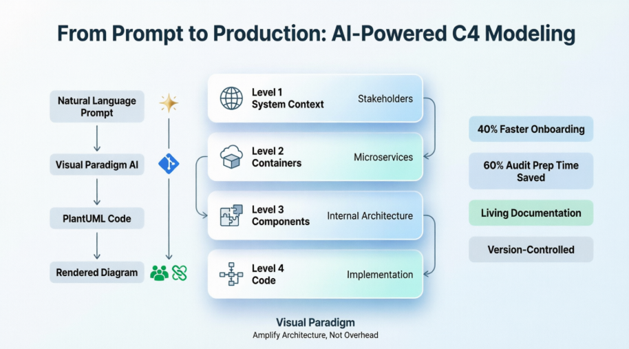
Yet even the best methodology requires the right tooling to thrive. This case study explores how Visual Paradigm's AI-powered C4 modeling capabilities bridge the gap between architectural theory and practical implementation. Through a real-world scenario—a cloud-native banking platform modernization—we demonstrate how teams can leverage natural language prompting, automated PlantUML generation, and hierarchical enforcement to create living, maintainable architecture documentation that evolves alongside the code.
Whether you're an enterprise architect scaling documentation across teams, a product manager aligning stakeholders, or a developer seeking clarity in complex systems, this guide shows how AI-enhanced C4 modeling transforms architecture from a static artifact into a collaborative, dynamic asset.
Before diving into the case study, a brief refresher on the C4 Model's foundational concepts:
Hierarchical Abstraction: Four levels of detail (System Context → Containers → Components → Code) let you zoom in/out based on audience needs
Audience-Driven Diagramming: Executives see Level 1; engineers see Levels 2–3; code reviewers optionally see Level 4
"Just Enough" Documentation: Avoid over-modeling; create diagrams only where they add clarity or reduce risk
Technology-Independent Notation: Focus on structure and relationships first; technology choices are annotations, not the diagram's purpose
These principles ensure C4 diagrams remain useful, maintainable, and relevant throughout a system's lifecycle.
A mid-sized financial technology company embarked on modernizing its legacy monolithic banking application into a cloud-native, microservices-based platform. The architecture team faced familiar hurdles:
Existing diagrams were scattered across Confluence, Visio, and whiteboard photos—none synchronized with the codebase
New team members spent weeks deciphering system boundaries and data flows
Security and compliance audits required up-to-date architecture views that were costly to produce manually
Product and engineering teams used different mental models, causing friction in planning sessions
The team adopted the C4 Model to bring structure to their documentation but quickly encountered adoption barriers: manual diagram maintenance was time-consuming, consistency across levels was hard to enforce, and keeping diagrams current felt like a separate project rather than part of the development workflow.
The team integrated Visual Paradigm's AI-powered C4 Studio into their architecture practice. The implementation followed a phased approach, leveraging natural language prompting to generate PlantUML diagrams at each C4 level.
Using the AI Diagram Generator, the lead architect described the banking platform in plain English:
"A mobile banking application used by customers to check balances, transfer funds, and pay bills. The system integrates with a core banking mainframe, a third-party payment gateway, and an external credit scoring service. Internal users include customer support agents and fraud analysts."
Within seconds, the AI generated a complete System Context Diagram in PlantUML format, correctly identifying:
The primary user (Customer) and internal users (Support Agent, Fraud Analyst)
The Mobile Banking System as the central software system
External dependencies: Core Banking Mainframe, Payment Gateway, Credit Scoring Service
Key relationships with directional flows and protocol annotations
The team refined the output through the conversational AI chatbot, asking it to "add regulatory reporting system as a dependency" and "highlight PCI-DSS boundary." The AI updated the PlantUML code instantly, maintaining syntactic correctness and visual consistency.
With the context established, the team drilled down into the Mobile Banking System. Using Visual Paradigm's hierarchical enforcement feature, they selected the system node and prompted:
"Break down the mobile banking system into containers: a React Native mobile app, an API Gateway, a User Service, a Transactions Service, and a Notifications Service. The API Gateway routes requests using OAuth2. Services communicate via asynchronous events through Kafka."
The AI generated a Container Diagram that:
Distinguished deployment units (mobile app, containers) from logical components
Annotated technology choices (React Native, Spring Boot, Kafka)
Mapped authentication flows and event-driven interactions
Preserved external system relationships from Level 1
For the high-risk Transactions Service, the team generated a Component Diagram to clarify internal structure:
"Show components within the Transactions Service: Transaction Controller, Validation Engine, Ledger Writer, Fraud Checker, and Event Publisher. The Validation Engine calls the Fraud Checker synchronously; successful transactions are written to the ledger and published as events."
The resulting diagram helped the team identify a circular dependency between Validation Engine and Fraud Checker—a design flaw that was corrected before implementation.
To support operational readiness, the team supplemented static views with:
Dynamic Diagrams: Illustrating the "Fund Transfer" use case across containers and components
Deployment Diagrams: Mapping containers to AWS infrastructure (EKS clusters, RDS instances, MSK Kafka)
Visual Paradigm's Interactive Navigator allowed stakeholders to toggle between views without losing context—product owners focused on System Context, engineers on Components, and SREs on Deployment—all from a single source of truth.
This section provides executable, syntax-validated PlantUML code for each C4 level. All examples use the official GitHub-hosted C4-PlantUML library for maximum compatibility with Visual Paradigm, PlantUML.com, and VS Code.
Implementation Note: The original
<C4/C4>include syntax can be unreliable across different PlantUML installations. All examples below use the standardized GitHub-hosted library links and have been sanitized to remove hidden characters that cause syntax errors.
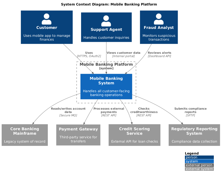
Purpose: Show the banking platform in its operational environment—who uses it and what external systems it depends on. Ideal for executives, product owners, and new team members.
@startuml
!include https://raw.githubusercontent.com/plantuml-stdlib/C4-PlantUML/master/C4_Context.puml

LAYOUT_WITH_LEGEND()

title System Context Diagram: Mobile Banking Platform

Person(customer, "Customer", "Uses mobile app to manage finances")
Person(support_agent, "Support Agent", "Handles customer inquiries")
Person(fraud_analyst, "Fraud Analyst", "Monitors suspicious transactions")

System_Boundary(banking_system, "Mobile Banking Platform") {
    System(mobile_banking, "Mobile Banking System", "Handles all customer-facing banking operations")
}

System_Ext(core_banking, "Core Banking Mainframe", "Legacy system of record")
System_Ext(payment_gateway, "Payment Gateway", "Third-party service for transfers")
System_Ext(credit_service, "Credit Scoring Service", "External API for loan checks")
System_Ext(regulatory_system, "Regulatory Reporting System", "Compliance data collection")

Rel(customer, mobile_banking, "Uses", "HTTPS, OAuth2")
Rel(support_agent, mobile_banking, "Views customer data", "Internal portal")
Rel(fraud_analyst, mobile_banking, "Reviews alerts", "Dashboard API")

Rel(mobile_banking, core_banking, "Reads/writes account data", "Secure MQ")
Rel(mobile_banking, payment_gateway, "Processes external payments", "REST API")
Rel(mobile_banking, credit_service, "Checks creditworthiness", "REST API")
Rel(mobile_banking, regulatory_system, "Submits compliance reports", "SFTP")
@enduml
What This Diagram Communicates
Scope: The Mobile Banking System is the boundary of our responsibility; everything else is external.
Actors: Three distinct user types with different access patterns and security requirements.
Dependencies: Four critical external systems, each with distinct integration protocols (MQ, REST, SFTP).
Security Boundary: The PCI-DSS compliance boundary implicitly includes the mobile banking system and its direct integrations.
Why It Matters
This diagram aligns stakeholders on what the system does and who it serves—before diving into how it's built. It's the foundation for risk assessments, integration planning, and roadmap discussions.
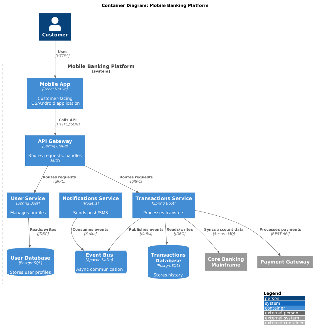
Purpose: Decompose the Mobile Banking System into deployable units (containers). Ideal for architects, DevOps engineers, and technical l
@startuml
!include https://raw.githubusercontent.com/plantuml-stdlib/C4-PlantUML/master/C4_Container.puml

LAYOUT_WITH_LEGEND()

title Container Diagram: Mobile Banking Platform

Person(customer, "Customer")
System_Ext(core_banking, "Core Banking Mainframe")
System_Ext(payment_gateway, "Payment Gateway")

System_Boundary(banking_boundary, "Mobile Banking Platform") {
    Container(mobile_app, "Mobile App", "React Native", "Customer-facing iOS/Android application")
    Container(api_gateway, "API Gateway", "Spring Cloud", "Routes requests, handles auth")
    Container(user_service, "User Service", "Spring Boot", "Manages profiles")
    Container(transaction_service, "Transactions Service", "Spring Boot", "Processes transfers")
    Container(notification_service, "Notifications Service", "Node.js", "Sends push/SMS")

    ContainerDb(user_db, "User Database", "PostgreSQL", "Stores user profiles")
    ContainerDb(transaction_db, "Transactions Database", "PostgreSQL", "Stores history")
    ContainerQueue(event_bus, "Event Bus", "Apache Kafka", "Async communication")
}

Rel(customer, mobile_app, "Uses", "HTTPS")
Rel(mobile_app, api_gateway, "Calls API", "HTTPS/JSON")
Rel(api_gateway, user_service, "Routes requests", "gRPC")
Rel(api_gateway, transaction_service, "Routes requests", "gRPC")

Rel(user_service, user_db, "Reads/writes", "JDBC")
Rel(transaction_service, transaction_db, "Reads/writes", "JDBC")
Rel(transaction_service, event_bus, "Publishes events", "Kafka")
Rel(notification_service, event_bus, "Consumes events", "Kafka")

Rel(transaction_service, core_banking, "Syncs account data", "Secure MQ")
Rel(transaction_service, payment_gateway, "Processes payments", "REST API")
@enduml
What This Diagram Communicates
Deployment Units: Five containers (mobile app, API gateway, three backend services) plus three infrastructure components (two databases, one message queue).
Technology Stack: Explicitly documents frameworks (Spring Boot, React Native), protocols (gRPC, Kafka), and data stores (PostgreSQL).
Communication Patterns: Synchronous API calls (gateway → services) vs. asynchronous event-driven flows (transaction service → notification service via Kafka).
Cloud Context: The boundary clarifies deployment environment for infrastructure planning.
Why It Matters
This view enables infrastructure provisioning, service ownership assignments, and resilience planning. It's the blueprint for your CI/CD pipelines and observability strategy.
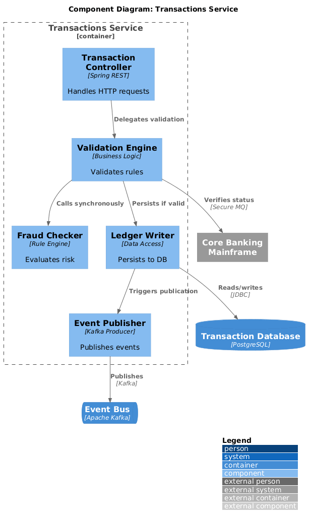
Purpose: Drill into the internal structure of a single container to clarify responsibilities and interactions. Ideal for developers working on that service.
@startuml
!include https://raw.githubusercontent.com/plantuml-stdlib/C4-PlantUML/master/C4_Component.puml

LAYOUT_WITH_LEGEND()

title Component Diagram: Transactions Service

Container_Boundary(transactions_svc, "Transactions Service") {
    Component(tx_controller, "Transaction Controller", "Spring REST", "Handles HTTP requests")
    Component(val_engine, "Validation Engine", "Business Logic", "Validates rules")
    Component(fraud_check, "Fraud Checker", "Rule Engine", "Evaluates risk")
    Component(ledger_writer, "Ledger Writer", "Data Access", "Persists to DB")
    Component(event_pub, "Event Publisher", "Kafka Producer", "Publishes events")
}

ContainerDb(tx_db, "Transaction Database", "PostgreSQL")
ContainerQueue(event_bus, "Event Bus", "Apache Kafka")
System_Ext(core_banking, "Core Banking Mainframe")

Rel(tx_controller, val_engine, "Delegates validation")
Rel(val_engine, fraud_check, "Calls synchronously")
Rel(val_engine, ledger_writer, "Persists if valid")
Rel(ledger_writer, tx_db, "Reads/writes", "JDBC")
Rel(ledger_writer, event_pub, "Triggers publication")
Rel(event_pub, event_bus, "Publishes", "Kafka")
Rel(val_engine, core_banking, "Verifies status", "Secure MQ")
@enduml
What This Diagram Communicates
Component Responsibilities: Clear separation of concerns—controller handles HTTP, validation enforces rules, fraud checker assesses risk, ledger writer manages persistence.
Critical Path: The synchronous call chain (controller → validation → fraud checker → ledger) highlights latency-sensitive operations.
Integration Points: External calls to Core Banking and asynchronous publishing to Kafka are explicitly modeled.
Data Flow: Shows how a transaction request flows through validation, persistence, and event emission.
Why It Matters
This level helps developers understand where to add new features, debug issues, or refactor code. It also reveals architectural risks—like the synchronous fraud check—that might benefit from async redesign.
Purpose: Illustrate key classes and design patterns within a component. Optional; use only for complex or critical logic. Ideal for code reviewers and new developers joining a module.
@startuml
!include https://raw.githubusercontent.com/plantuml-stdlib/C4-PlantUML/master/C4_Component.puml
' Standard UML Class styling
skinparam class {
BackgroundColor White
ArrowColor #2C3E50
BorderColor #2C3E50
}
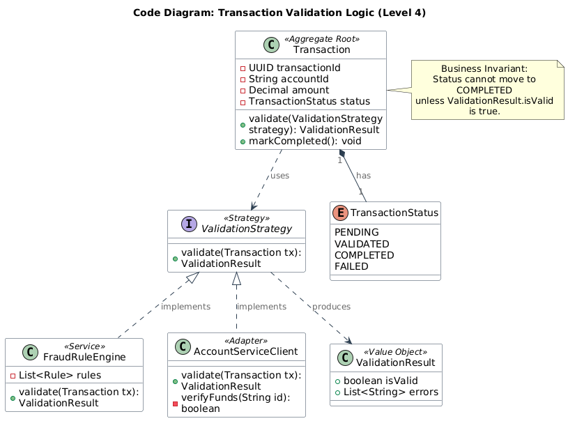
title Code Diagram: Transaction Validation Logic (Level 4)
class Transaction <<Aggregate Root>> {
- UUID transactionId
- String accountId
- Decimal amount
- TransactionStatus status
+ validate(ValidationStrategy strategy): ValidationResult
+ markCompleted(): void
}
interface ValidationStrategy <<Strategy>> {
+ validate(Transaction tx): ValidationResult
}
class FraudRuleEngine <<Service>> {
- List<Rule> rules
+ validate(Transaction tx): ValidationResult
}
class AccountServiceClient <<Adapter>> {
+ validate(Transaction tx): ValidationResult
- verifyFunds(String id): boolean
}
class ValidationResult <<Value Object>> {
+ boolean isValid
+ List<String> errors
}
enum TransactionStatus {
PENDING
VALIDATED
COMPLETED
FAILED
}
' Relationships
Transaction "1" *-- "1" TransactionStatus : has
Transaction ..> ValidationStrategy : uses
ValidationStrategy <|.. FraudRuleEngine : implements
ValidationStrategy <|.. AccountServiceClient : implements
ValidationStrategy ..> ValidationResult : produces
note right of Transaction
Business Invariant:
Status cannot move to COMPLETED
unless ValidationResult.isValid is true.
end note
@enduml
What This Diagram Communicates
Domain Model: The Transaction aggregate root encapsulates business rules and state transitions.
Design Pattern: Strategy pattern (ValidationStrategy) allows pluggable validation rules while keeping the domain entity decoupled from infrastructure concerns.
DDD Alignment: Stereotypes like <<Aggregate Root>> and <<Value Object>> align with Domain-Driven Design principles common in microservices.
Key Invariant: The note explicitly documents the business rule that must be enforced in code, bridging architecture and implementation.
Why It Matters
This level bridges architecture and implementation. It helps ensure that code structure reflects architectural intent and makes complex logic accessible during onboarding or refactoring.
Implementation Tip: Since Level 4 is the most granular, keep these diagrams focused on a single Bounded Context or specific complex algorithm rather than mapping entire schemas. Use this for the "tricky" parts of code where visual clarity prevents bugs.
Documentation Velocity: Architecture diagrams that previously took 2-3 days to draft and validate were generated and refined in under 30 minutes
Onboarding Efficiency: New engineers reached productive contribution 40% faster, citing clear, navigable architecture maps as a key factor
Audit Readiness: Compliance teams received up-to-date, exportable diagrams for security reviews, reducing preparation time by 60%
Design Quality: Early visualization of component interactions helped catch 3 significant architectural anti-patterns before code was written
Shared Language: The C4 hierarchy created a common vocabulary—"Let's discuss this at the container level"—reducing ambiguity in cross-functional meetings
Living Documentation: By storing diagrams as PlantUML in Git, architecture evolved naturally with the codebase; stale diagrams became a thing of the past
Inclusive Collaboration: Non-technical stakeholders could engage with System Context diagrams, while engineers dove into Components—each audience received the right level of detail without overwhelm
Start with Audience: The team always defined the diagram's consumer first (executive, developer, auditor), then selected the appropriate C4 level
Iterate with AI, Validate with Humans: AI accelerated draft creation, but architecture reviews remained essential for validating design intent
Integrate into Workflow: Diagrams were treated as code—reviewed in PRs, versioned, and linked to ADRs (Architecture Decision Records)
Embrace "Just Enough": The team resisted over-documenting; Level 4 code diagrams were generated only for complex or critical modules
The team evaluated multiple C4 tools before selecting Visual Paradigm. Key differentiators included:
AI-Native Workflow: Unlike tools requiring manual diagramming or separate code editors, Visual Paradigm's conversational AI allowed rapid iteration without context switching
Full C4 Coverage: Support for all six views (Context, Container, Component, Landscape, Dynamic, Deployment) in a unified environment eliminated tool fragmentation
PlantUML First: Generating standards-compliant PlantUML ensured diagrams were portable, version-controllable, and renderable in any PlantUML-compatible viewer
Enterprise Integration: Export options (JSON, PNG, PDF) and shareable read-only links facilitated distribution across security boundaries
Accessibility Tiers: The web-based AI Studio enabled quick prototyping for consultants, while Desktop and Online editions supported deeper integration for core teams
Visual Paradigm offers multiple ways to access these AI C4 features:
AI-Powered C4 PlantUML Studio (Web): A specialized web-based tool for rapid prototyping where speed and code-first approaches are prioritized
Visual Paradigm Desktop: Professional Edition or higher users can access the AI studio directly via the application toolbar (Tools > App)
Visual Paradigm Online: Available to users with a Combo Edition or higher subscription
Beyond AI generation, the platform provides standard C4 modeling tools:
Drag-and-Drop Editor: For manual refinement, offering easy-to-use tools to format shapes and connectors
Interactive Navigator: A live, resizable tree panel that allows users to switch between different system elements and diagram levels seamlessly
Export and Sharing: Diagrams can be exported as JSON or PlantUML code, or shared with stakeholders via read-only links
✅ Start at Level 1: Always define system boundaries and actors before diving into technical details.
✅ Use Validated PlantUML: Use GitHub-hosted C4-PlantUML library links for maximum compatibility across tools and environments.
✅ Use AI for Drafting, Humans for Refining: Let Visual Paradigm's AI generate initial PlantUML from natural language, then validate design intent with your team.
✅ Keep Level 4 Optional: Only model code-level details for complex or high-risk components—avoid diagramming every class.
✅ Treat Diagrams as Code: Store PlantUML files in Git, review them in pull requests, and version them alongside your application code.
✅ Navigate Hierarchically: Use tooling that supports jumping between levels to maintain context and reduce cognitive load.
By applying these principles consistently, teams transform architecture documentation from a static artifact into a dynamic, collaborative asset that scales with system complexity and organizational growth.
The fusion of the C4 Model's structured abstraction with AI-powered tooling represents a paradigm shift in software architecture communication. As demonstrated in this banking platform modernization case study, teams can move from fragmented, static diagrams to dynamic, living documentation that scales with system complexity and organizational growth.
Visual Paradigm's AI-enhanced C4 Studio doesn't replace architectural thinking—it amplifies it. By handling the mechanical overhead of diagram creation, notation consistency, and hierarchical enforcement, the tool frees architects and engineers to focus on what matters: designing resilient systems, aligning stakeholders, and delivering value.
The future of architecture documentation isn't more diagrams—it's smarter diagrams. Diagrams that generate from conversation, evolve with code, and adapt to their audience. The C4 Model provides the framework; AI provides the acceleration. Together, they transform architecture from a documentation burden into a strategic asset.
For teams ready to elevate their architecture practice, the path is clear: start with your system context, embrace iterative refinement, and let AI handle the heavy lifting. The result isn't just better diagrams—it's better software, built by teams who share a common, evolving understanding of the systems they create.
AI Diagram Generator: Complete C4 Model Support: Overview of Visual Paradigm's AI capabilities for generating all C4 model diagram types from natural language descriptions.
AI-Powered C4 PlantUML Studio: Web-based tool for rapid C4 diagram prototyping using AI-driven PlantUML generation.
C4 Diagram Tool Features: Detailed breakdown of Visual Paradigm's native C4 modeling capabilities, including drag-and-drop editing and hierarchical navigation.
Leveraging Visual Paradigm's AI C4 Studio: A Comprehensive Guide: Third-party guide exploring practical workflows for AI-assisted C4 documentation.
Visual Paradigm AI C4 Tutorial Video: Video demonstration of generating and refining C4 diagrams using Visual Paradigm's AI chatbot interface.
Visual Paradigm Online: AI and Collaboration Features: Documentation on integrating AI-powered tools, online diagramming, and version-controlled repositories across Visual Paradigm editions.
Mastering C4 Diagrams in Visual Paradigm: Hands-On Review: Comparative review of manual, template-based, code-import, and AI-driven methods for creating C4 diagrams.
AI-Powered C4 PlantUML Markdown Editor: Announcement of Markdown integration for C4 modeling, enabling documentation and diagrams in a single workflow.
C4 PlantUML Studio Features: Technical overview of the PlantUML-focused studio environment for code-first architecture modeling.
C4 Model Tool: Easy Drag-and-Drop Features: Feature highlight of Visual Paradigm Online's intuitive interface for formatting C4 diagram elements.
AI-Powered C4: Online Banking Architecture Example: Real-world example demonstrating end-to-end C4 modeling for a financial services use case using AI generation.
@startuml
!include https://raw.githubusercontent.com/plantuml-stdlib/C4-PlantUML/master/C4_Context.puml
!include https://raw.githubusercontent.com/plantuml-stdlib/C4-PlantUML/master/C4_Container.puml
!include https://raw.githubusercontent.com/plantuml-stdlib/C4-PlantUML/master/C4_Component.puml

LAYOUT_WITH_LEGEND()

title [Diagram Title]: [System Name]

' Define actors
Person(actor1, "Actor Name", "Description")

' Define system boundary
System_Boundary(system_boundary, "System Name") {
    Container(container1, "Container Name", "Technology", "Responsibility")
    ContainerDb(db1, "Database Name", "Technology", "Purpose")
}

' Define external systems
System_Ext(external1, "External System", "Purpose")

' Define relationships
Rel(actor1, container1, "Uses", "Protocol")
Rel(container1, db1, "Reads/writes", "JDBC")
Rel(container1, external1, "Calls", "REST API")
@enduml
| Audience | Recommended C4 Level | Key Questions Answered |
|---|---|---|
| Executives / Product Owners | Level 1: System Context | What does the system do? Who uses it? What does it depend on? |
| Architects / Tech Leads | Level 2: Container | How is the system deployed? What technologies are used? How do services communicate? |
| Developers | Level 3: Component | What are the internal responsibilities? How do components interact? Where do I add new features? |
| Code Reviewers / New Hires | Level 4: Code (Optional) | How is this complex logic structured? What are the key domain invariants? |
Be Specific About Boundaries: "Show the Mobile Banking System and its external dependencies" yields better results than "Draw a banking system."
Specify Technologies Explicitly: "Use Spring Boot for services, React Native for mobile, Kafka for events" ensures accurate annotations.
Iterate Incrementally: Generate Level 1 first, then prompt "Now break down the Mobile Banking System into containers..."
Use Conversational Refinement: After generation, ask the AI to "Add a regulatory reporting system" or "Highlight the PCI-DSS boundary."
Validate Output: Always review AI-generated PlantUML for logical consistency before committing to your repository.