
Translating abstract business requirements into a robust, scalable software architecture is one of the most critical challenges in software engineering. Without a structured approach, systems quickly become tangled webs of poorly defined objects and redundant data.
To combat this, software architects rely on a systematic and iterative process for building structural models (primarily class diagrams). This guide outlines a proven methodology for defining software architecture and data elements, moving from raw text analysis to formalized UML diagrams. By leveraging noun analysis, CRC cards, and data dictionaries, development teams can ensure their structural models are cohesive, consistent, and perfectly aligned with system requirements.
Before diving into the step-by-step process, here are the foundational concepts that drive structural modeling:
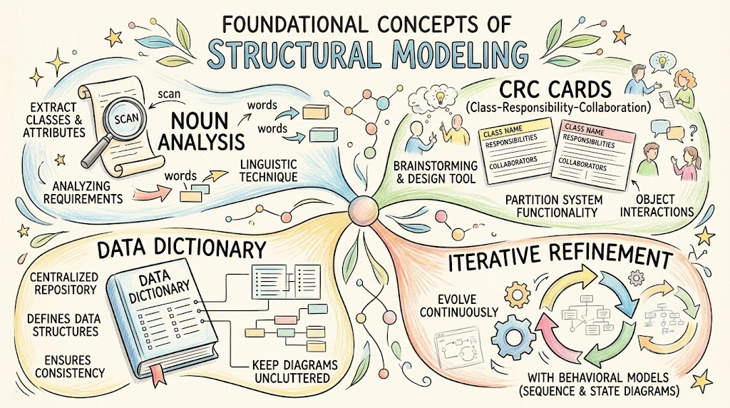
Noun Analysis: The linguistic technique of extracting potential classes and attributes from requirement documents.
CRC Cards (Class-Responsibility-Collaboration): A brainstorming and design tool used to partition system functionality and define object interactions.
Data Dictionary: A centralized repository that defines data structures, ensuring consistency and keeping visual diagrams uncluttered.
Iterative Refinement: The understanding that structural models are not created in a vacuum; they evolve continuously alongside behavioral models (like sequence and state diagrams).
The foundation of any structural model is finding the "right" classes. This is typically initiated through Noun Analysis, a technique that bridges the gap between business language and object-oriented design.
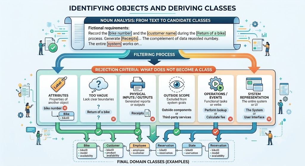
Developers begin by examining a concise description of system requirements—such as a Problem Definition, Business Rules, or Use Case descriptions. They read through the text and underline all nouns and noun phrases. These underlined terms become the initial candidate pool for classes and attributes.
Not every noun becomes a class. To maintain a clean and logical architecture, candidates are rigorously filtered. Nouns are rejected and reclassified if they fall into the following categories:
Attributes: Concepts that are clearly properties of another object. (e.g., In "Record the bike number", "bike number" is an attribute of the Bike class, not a class itself).
Too Vague: Concepts that lack clear boundaries or definitions. (e.g., "Return of a bike" is an event or action, not a tangible class).
Physical Inputs/Outputs: Items that are merely reports or outputs generated from stored data. (e.g., "Receipts" or "Lists" do not need to be core domain classes if they are just printed outputs).
Outside Scope: Anything explicitly excluded from the current system's goals.
Operations/Events: Functional tasks or verbs disguised as nouns that lack associated persistent data.
System Representation: Nouns that represent the entire system or the UI itself rather than its constituent domain parts. (e.g., "The System", "The Screen").
Once the candidate classes are identified, CRC (Class-Responsibility-Collaboration) cards are used to define what each class actually does and how it interacts with others.
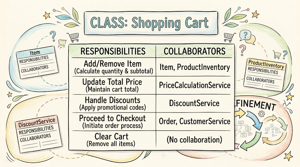
CRC cards are often physical index cards used in collaborative design sessions.
The Front: Contains a high-level description or a visual icon representing the class.
The Back: Divided into two columns:
Responsibilities: The services, behaviors, or data the class manages.
Collaborations: The other classes this class must interact with (send messages to) to fulfill its responsibilities.
Design Principle: To ensure high cohesion and low coupling, a general rule of thumb is that no class should have more than three or four responsibilities. If a card overflows, the class is likely doing too much and should be split.
CRC cards are highly interactive. Teams use them in role-play sessions where members "enact" use case scenarios. As a scenario progresses, the team passes the "turn" to the card that holds the next responsibility, naturally discovering necessary message passing and refining the collaborations.
As the model grows, UML diagrams can become visually overwhelming. The Data Dictionary acts as the central repository for the agreed-upon terms, meanings, and detailed structures used in the system.
Uncluttering Diagrams: UML diagrams require short, readable labels. The data dictionary stores exhaustive details about attributes and operations, allowing the visual model to remain clean and focused on relationships.
Consistency: Built in parallel with other diagrams, it acts as a single source of truth. It cross-references class, state, and interaction diagrams to ensure a term like customerId means the exact same thing everywhere.
The data dictionary uses a semi-formal notation to define complex structures succinctly:
= means "consists of" or "is defined as".
+ means "and" (concatenation of elements).
{ } indicates repeating attributes or collections.
Example: Rental = rentalId + startDate + endDate + {costBreakdown}
(This defines a Rental as consisting of an ID, start date, and end date, along with a repeating list/collection of cost breakdowns).
There is no single "correct" way to start building the structural model. The sources suggest two primary strategies, both of which feed into the same iterative loop:
Use Case Realization (Bottom-Up): Analyze each use case one by one. Determine the required classes and collaborations to fulfill that specific use case, then merge these localized diagrams into a unified, system-wide class diagram. This ensures every class has a clear trace to a business requirement.
Domain Modeling (Top-Down): Develop a single, comprehensive class diagram that attempts to capture all relevant classes in the problem domain simultaneously, focusing on the real-world entities and their relationships before worrying about specific use case flows.
The Iterative Nature:
Regardless of the starting point, the process is iterative. As the team builds behavioral models (like Sequence Diagrams or State Machines), they will inevitably discover missing attributes, incorrect relationships, or new classes. The structural class diagram must be continuously refined and corrected to reflect these behavioral insights.
Below are PlantUML examples demonstrating the output of this structural modeling process. We will use a Bike Rental System to illustrate the concepts.
This diagram represents the final structural model after applying Noun Analysis (rejecting "Receipt" as a physical output, keeping it simple, and identifying "Bike Status" as an enum). It reflects the clean structure achieved by offloading verbose details to the Data Dictionary.
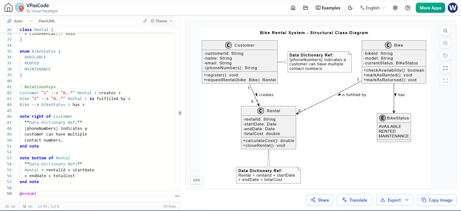
@startuml
skinparam classAttributeIconSize 0
skinparam monochrome true
skinparam shadowing false

title Bike Rental System - Structural Class Diagram

class Customer {
  - customerId: String
  - name: String
  - email: String
  - {phoneNumbers}: String
  + register(): void
  + requestRental(bike: Bike): Rental
}

class Bike {
  - bikeId: String
  - model: String
  - currentStatus: BikeStatus
  + checkAvailability(): boolean
  + markAsRented(): void
  + markAsReturned(): void
}

class Rental {
  - rentalId: String
  - startDate: Date
  - endDate: Date
  - totalCost: double
  + calculateCost(): double
  + closeRental(): void
}

enum BikeStatus {
  AVAILABLE
  RENTED
  MAINTENANCE
}

' Relationships
Customer "1" --> "0..*" Rental : creates >
Bike "1" --> "0..*" Rental : is fulfilled by >
Bike --> BikeStatus : has >

note right of Customer
  **Data Dictionary Ref:**
  {phoneNumbers} indicates a
  customer can have multiple
  contact numbers.
end note

note bottom of Rental
  **Data Dictionary Ref:**
  Rental = rentalId + startDate
  + endDate + totalCost
end note

@enduml
If the team chose the Use Case Realization strategy, they would start by mapping the actors and use cases to ensure the structural model covers all functional requirements.
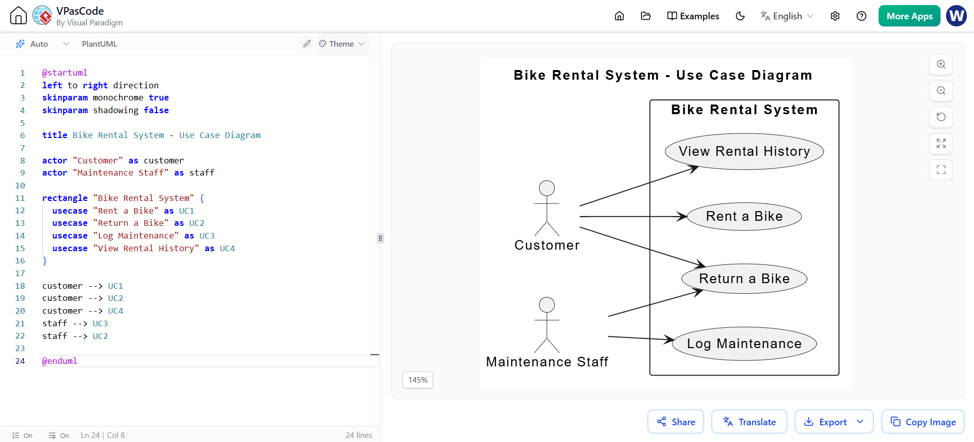
@startuml
left to right direction
skinparam monochrome true
skinparam shadowing false

title Bike Rental System - Use Case Diagram

actor "Customer" as customer
actor "Maintenance Staff" as staff

rectangle "Bike Rental System" {
  usecase "Rent a Bike" as UC1
  usecase "Return a Bike" as UC2
  usecase "Log Maintenance" as UC3
  usecase "View Rental History" as UC4
}

customer --> UC1
customer --> UC2
customer --> UC4
staff --> UC3
staff --> UC2

@enduml
Building a structural model is not a mere administrative task; it is the architectural blueprint of your software. By systematically applying Noun Analysis, you ensure that your classes are grounded in actual business requirements rather than assumptions. By utilizing CRC Cards, you guarantee that responsibilities are well-partitioned and collaborations are clearly defined. Finally, by maintaining a rigorous Data Dictionary, you preserve consistency and readability across your entire design.
Remember that software design is inherently iterative. Your initial class diagram is a living document. As you dive deeper into behavioral modeling and system dynamics, do not be afraid to refactor, split, or merge classes. A well-crafted structural model is the ultimate key to delivering software that is maintainable, scalable, and perfectly aligned with the problem domain.

